Solar Tower With Integrated Gas Turbine

a solar tower and gas turbine technology, applied in the direction of electric generator control, lighting and heating apparatus, machines/engines, etc., can solve the problems of limiting the maximum efficiency of the solar tower, the temperature to which the fluid can be heated to approximately 750°, and the superficial receivers have the same technical limits as boilers, so as to achieve the effect of minimizing energy loss

Inactive Publication Date: 2013-06-13
ALSTOM TECH LTD
View PDF13 Cites 12 Cited by
  • Summary
  • Abstract
  • Description
  • Claims
  • Application Information

AI Technical Summary

Benefits of technology

[0022]The described solar tower is advantageous over the prior art as it allows the most compact mounting of the gas turbine engine and the solar energy receiver in the tower and it minimizes energy loss resulting from the transport of heat from the solar energy receiver means to the gas turbine. It does this by integrating the solar energy receiver with the gas heating arrangement of the gas turbine and thereby removing the need to transport the heat from the solar energy receiver to a gas turbine separate from the energy receiver. That is, t

Problems solved by technology

As a result, superficial receivers have the same technical limits as boilers.
This limits the temperature to which the fluid can be heated to approximately 750° C. and correspondingly limits the maximum efficiency of the solar towe

Method used


Image

  • Solar Tower With Integrated Gas Turbine
  • Solar Tower With Integrated Gas Turbine
  • Solar Tower With Integrated Gas Turbine

Examples


Embodiment Construction

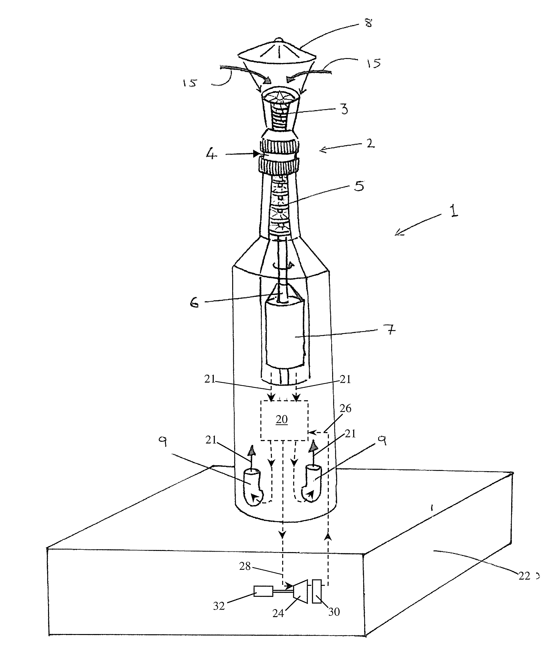
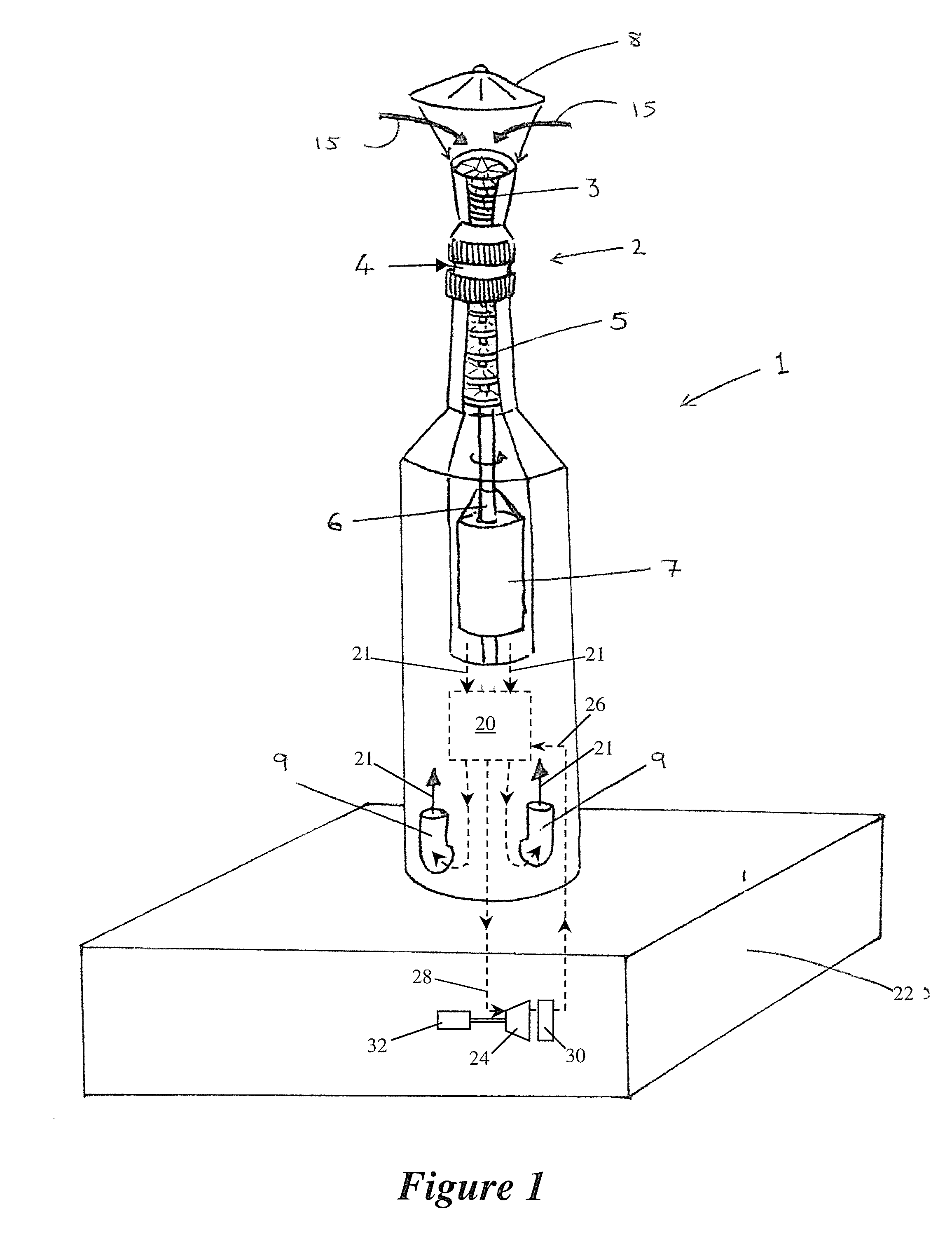
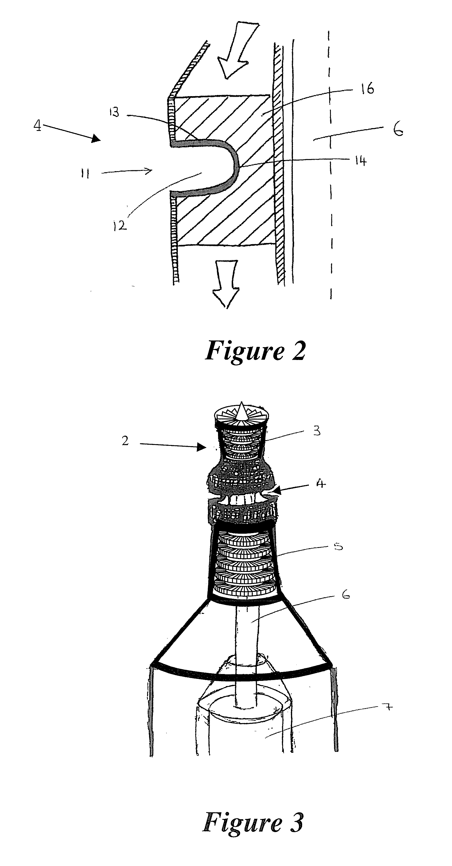
[0041]A preferred exemplary embodiment of a solar tower 1 is illustrated in FIG. 1. The solar tower 1 has a gas turbine engine 2 integrally and vertically mounted substantially at an upper end of the tower. The gas turbine engine 2 includes a compressor 3 mounted above a sealed volumetric solar radiation receiver 4, and a turbine 5, mounted below the volumetric receiver. The volumetric receiver 4 forms the gas heating arrangement of the gas turbine engine 2.

[0042]The solar tower 1 is located within a solar field (not shown) having a large number of reflectors that act to reflect solar radiation incident upon them onto the sealed volumetric receiver 4.

[0043]The compressor 3 and turbine 5 of the gas turbine engine 2 are mounted on a drive shaft 6. The drive shaft 6 extends vertically downwards from the gas turbine engine 2 to drive a generator 7 that is also vertically mounted within the solar tower 1.

[0044]A protective roof 8 is mounted above the upper end of the solar tower 1. In FI...


PUM


Abstract

A solar tower (1) has a solar radiation receiver (4) and a gas turbine engine (2). The gas turbine engine (2) is vertically arranged within the tower and includes, in downward flow series:
    • a compressor (3) for compressing ambient air (15) drawn through at least one air inlet at an upper end of the tower,
    • a heating arrangement (4) for heating compressed air from the compressor, the solar radiation receiver includes at least part of the heating arrangement, and
    • a turbine (5) for extracting work from the heated compressed air.
The gas turbine engine (2) is integrally formed with the solar tower (1) and the gas heating arrangement of the gas turbine engine (2) is integrally formed with the solar radiation receiver (4).

Description

[0001]This application is a Continuation of, and claims priority under 35 U.S.C. §120 to, International App. No. PCT / EP2011 / 063532, filed 5 Aug. 2011, and claims priority therethrough under 35 U.S.C. §§119, 365 to German App. No. 10 2010 036 900.4, filed 6 Aug. 2010, the entireties of which are incorporated by reference herein.BACKGROUND[0002]1. Field of Endeavor[0003]The present disclosure relates to concentrated solar power, and in particular to an advantageous combination of a solar power tower with a gas turbine engine to generate electricity.[0004]2. Brief Description of the Related Art[0005]Concentrated solar power involves the use of lenses, mirrors or other optical apparatus to focus solar radiation from a large incident area onto a small area. The energy from the solar radiation is then used to generate power. Concentrated solar power is expected to become an important energy source in the future.[0006]There have been many proposals for concentrated solar power technology. ...

Claims


Application Information

Patent Timeline
IPC IPC(8): F03G6/04H02K7/18F02C1/10F24S10/80F24S20/20
CPCF02C1/05F02C6/18F03G6/064F24J2/07F24J2/28F24J2002/4685Y02E10/41F03G6/067F02C1/10F03G6/04H02K7/1823Y02E10/44Y02E10/46Y02B10/20F24S10/80F24S20/20F24S2080/011Y02E10/40
Inventor WIEGHARDT, KAI
Owner ALSTOM TECH LTD
Why Eureka
Try Eureka