Oscillatory wave drive unit and image stabilization device

a technology of oscillatory wave and drive unit, which is applied in the direction of television system, instruments, printing, etc., can solve the problems of energy loss and therefore power loss, and achieve the effect of reducing power loss

Active Publication Date: 2013-06-13
CANON KK
View PDF6 Cites 10 Cited by
  • Summary
  • Abstract
  • Description
  • Claims
  • Application Information

AI Technical Summary

Benefits of technology

[0010]According to the present invention, an oscillatory wave drive unit has a mechanism that when a force acts on a vibrator in a direction different from the driving direction, moves the vibrator in the direction in which the force acts. Therefore, power loss can be reduced without increasing power consumption of an oscillatory wave drive unit and an image stabilization device.

Problems solved by technology

However, combining a plurality of oscillatory wave drive units has the following serious problem to be solved.
The frictional force due to the contact between the moving body and the oscillatory wave drive units interferes with the movement of the moving body and causes energy loss and therefore power loss.

Method used


Image

  • Oscillatory wave drive unit and image stabilization device
  • Oscillatory wave drive unit and image stabilization device
  • Oscillatory wave drive unit and image stabilization device

Examples


first embodiment

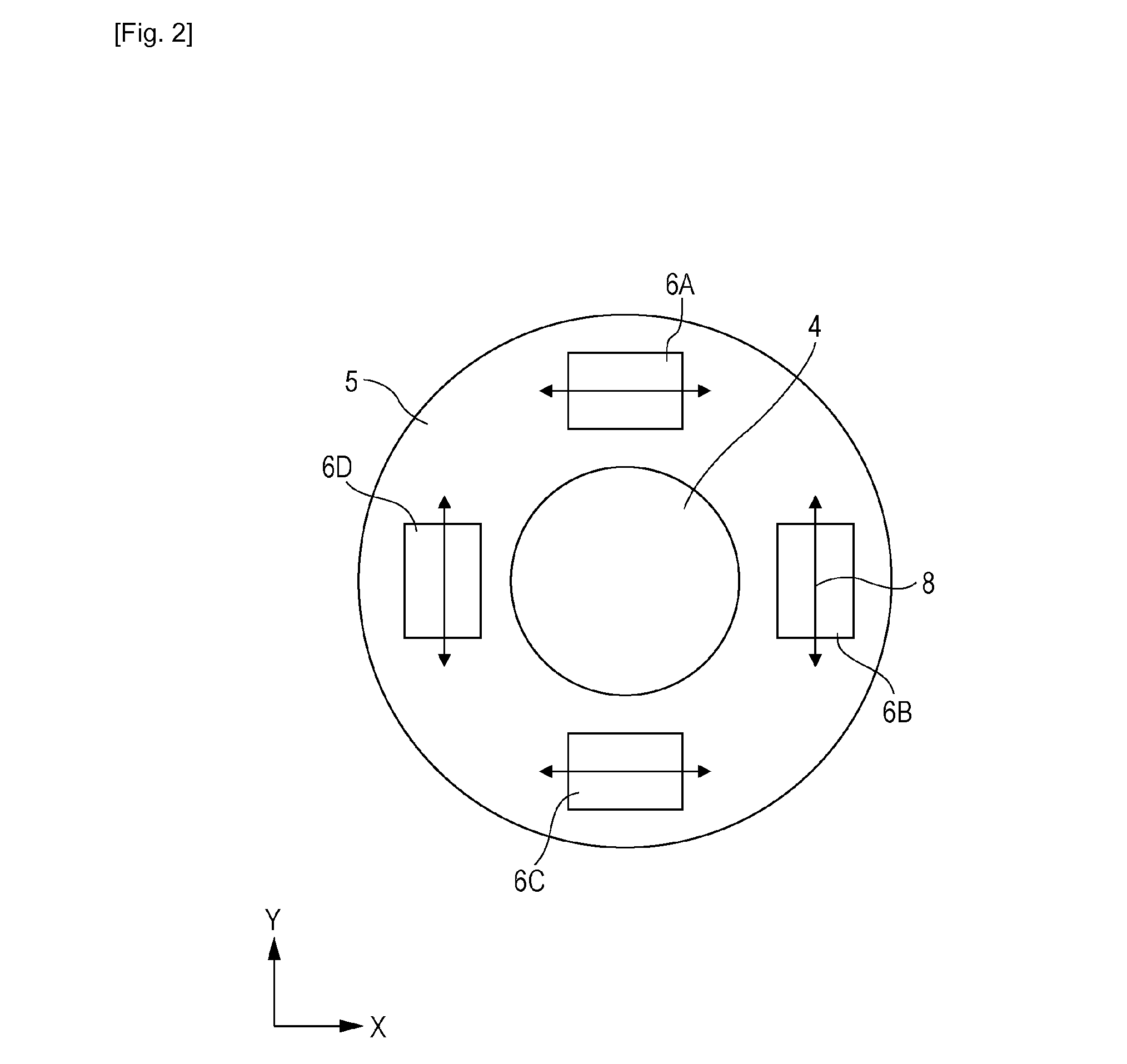
[0037]FIG. 3 is a sectional view of a camera as an imaging apparatus according to a first embodiment of the present invention. The camera of FIG. 3 can take moving and still pictures. Reference numeral 1 denotes a lens barrel, and reference numeral 2 denotes a camera body. Reference numeral 3 denotes an image stabilization device built in the lens barrel 1. The unit 3 includes an optical lens 4, a moving body 5 holding the optical lens 4, oscillatory wave drive units 6 that move the moving body 5.

[0038]Although not shown in FIG. 3, the lens barrel 1 is provided with an optical system other than the optical lens 4, an acceleration sensor that detects a shake of the lens barrel 1, an encoder that detects the two-dimensional movement of the moving body. The lens barrel 1 is further provided with a power source that supplies electric energy to the oscillatory wave drive units 6, and a control unit that processes a signal output from the acceleration sensor and a signal output from the e...

second embodiment

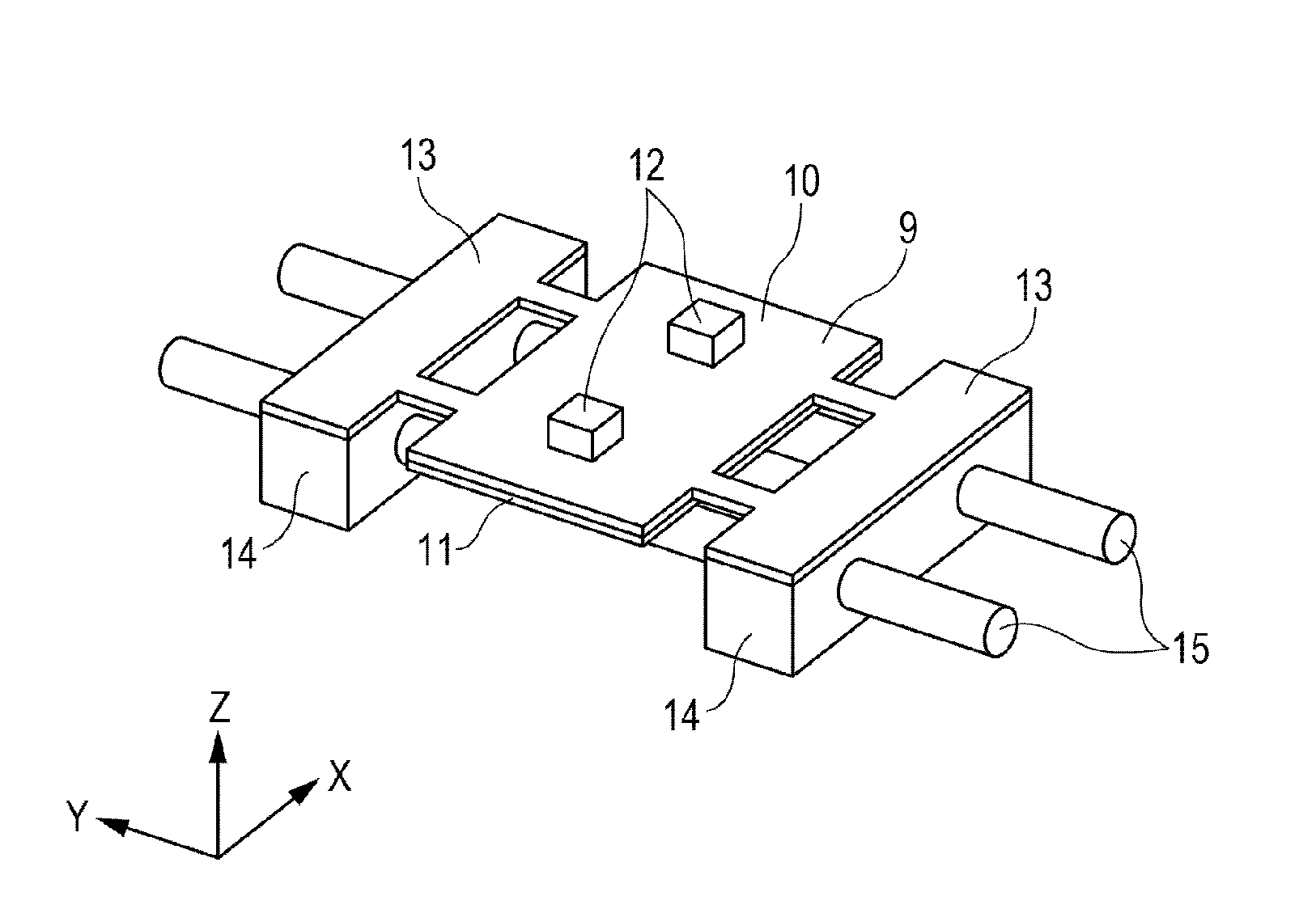
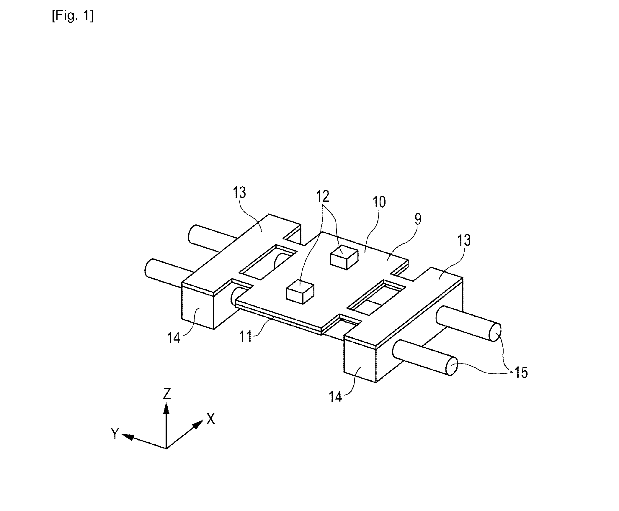
[0051]FIG. 5A is a perspective view of an oscillatory wave drive unit according to another embodiment of the present invention as viewed from the protrusions 12 side. FIG. 5B is a perspective view of the oscillatory wave drive unit as viewed from the side opposite to the protrusions 12. The coordinate system in the figures is a right-handed rectangular coordinate system. A description will be given with reference to the two figures.

[0052]This embodiment differs from the first embodiment in the configuration of the vibrator and the securing portion, and the configuration for holding the vibrator. A holder 20 is coupled to securing portions 13 of a vibrator 9 and has a square frame-like shape. A spring 17 that is an elastic member is attached to the holder 20. The holder 20 holds a magnet 16 in a space between the vibrator 9 and the spring 17.

[0053]The spring 17 is made by pressing a sheet of stainless steel spring material. However, the configuration of springs usable in the present ...

third embodiment

[0055]FIG. 6 is a perspective view of an oscillatory wave drive unit according to another embodiment of the present invention as viewed from the side opposite to the protrusions 12. The coordinate system in the figure is a right-handed rectangular coordinate system.

[0056]This embodiment differs from the second embodiment in that a spring 17 includes two Y-deforming springs 18 in the Y direction (second direction) in the figure, and two securing portions 19 at the ends the Y-deforming springs 18. The two securing portions 19 are secured to a lens barrel 1 (not shown). This configuration is, elastically, a parallel crank mechanism in the Y direction (second direction). When the vibrator 9 is subjected to a force in the Y direction from the moving body 5, the vibrator 9 is not prone to rotary motion in the XZ plane and moves mainly in the Y direction. In this embodiment, as in the second embodiment, the thickness direction of the Y-deforming springs 18 is the Y direction (second direct...


PUM


Abstract

An oscillatory wave drive unit includes at least one vibrator having an electromechanical energy converting element, and at least one supporting member configured to support the at least one vibrator. The oscillatory wave drive unit excites oscillation in the at least one vibrator and moves a moving body in contact with the at least one vibrator by frictional force. The oscillatory wave drive unit includes at least one moving mechanism configured to support the at least one vibrator movably in a plane parallel to the plane where the at least one vibrator and the moving body are in contact with each other, in a second direction intersecting with a first direction in which the at least one vibrator drives the moving body.

Description

TECHNICAL FIELD[0001]The present invention relates to an oscillatory wave drive unit and an image stabilization device including the same.BACKGROUND ART[0002]Many oscillatory wave drive units have been proposed that excite oscillation in a vibrator and move a moving body pressed against the vibrator. These are positioned as important functional components in optical instruments that must operate particularly precisely. PTL 1 and PTL 2 disclose combining a plurality of straight-type oscillatory wave drive units that can each move a moving body linearly, to move a moving body in two-dimensional directions for use as an image stabilization device.[0003]However, combining a plurality of oscillatory wave drive units has the following serious problem to be solved. When a moving body is moved in some directions, the moving direction of the moving body and the driving direction of some of the plurality of oscillatory wave drive units intersect at right angles or at close to right angles. In...

Claims


Application Information

Patent Timeline
Patent Type & Authority Applications(United States)
IPC IPC(8): H02N2/00G03B5/00
CPCG02B27/646G03B5/00G03B2205/0015G03B2205/0061H02N2/0015H02N2/001H02N2/028H04N5/2254H04N5/23258H04N5/2328H02N2/026H04N23/55H04N23/685H04N23/6812
Inventor OHASHI, KAISHISEKI, HIROYUKITSUKIMOTO, TAKAYUKIYAMAMOTO, SHINJI
Owner CANON KK
Why Eureka
Try Eureka