
High-brightness spatial-multiplexed multi-emitter pump with tilted collimated beam

a multi-emitter pump and beam beam technology, applied in semiconductor lasers, laser details, electrical devices, etc., can solve the problems of low coupling efficiency (ce), impractical to create different packages for different target power levels, and space or “pitch” between laser bars in particular stacks, so as to reduce optical component feedback, increase the reliability of laser diodes, and high coupling efficiency

Active Publication Date: 2013-06-13
LUMENTUM OPERATIONS LLC
View PDF2 Cites 44 Cited by
  • Summary
  • Abstract
  • Description
  • Claims
  • Application Information

AI Technical Summary

Benefits of technology

This patent describes a new way to make laser diodes that have a single output but can emit light in different directions. This is accomplished by using multiple diodes that are stacked in a staircase formation. The design of the laser diodes also includes a tilted collimated output beam, which helps to reduce feedback from optical components and makes the laser more reliable. The technical effect of this design is that it allows for more flexible and efficient use of the diodes, resulting in higher overall performance and reliability of the laser system.

Problems solved by technology

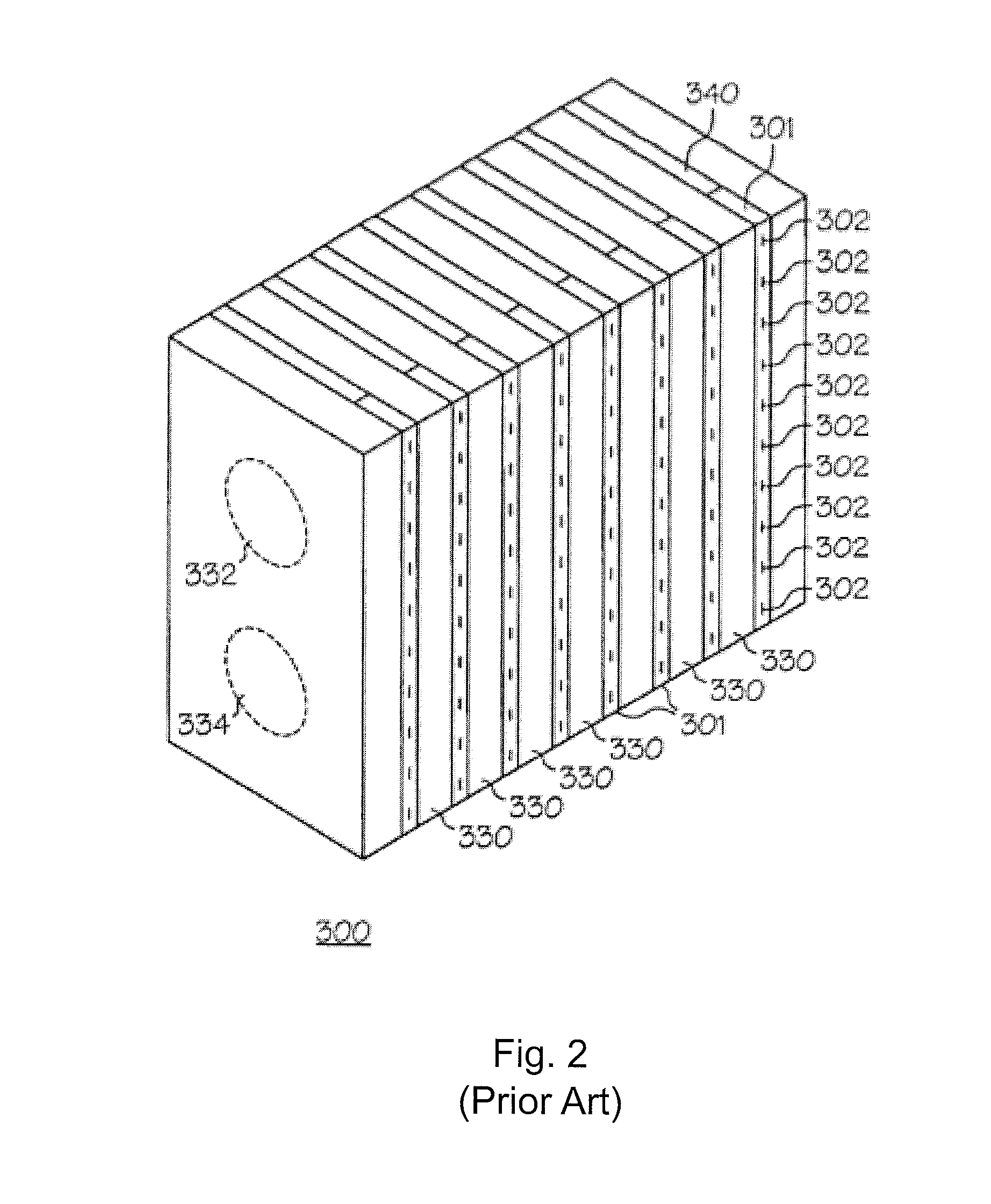
One limitation of the attainable brightness of stacked laser bar assemblies, such as 300, is the spacing or “pitch” between laser bars in the particular stack.
However, while a smaller step height can combine more emitters, it may also cause beam clipping, which results in a lower coupling efficiency (CE).
Unfortunately, it is impractical to create different packages for different target power levels (i.e., different number of emitters per pump).

Method used


Image

  • High-brightness spatial-multiplexed multi-emitter pump with tilted collimated beam
  • High-brightness spatial-multiplexed multi-emitter pump with tilted collimated beam
  • High-brightness spatial-multiplexed multi-emitter pump with tilted collimated beam

Examples


Embodiment Construction

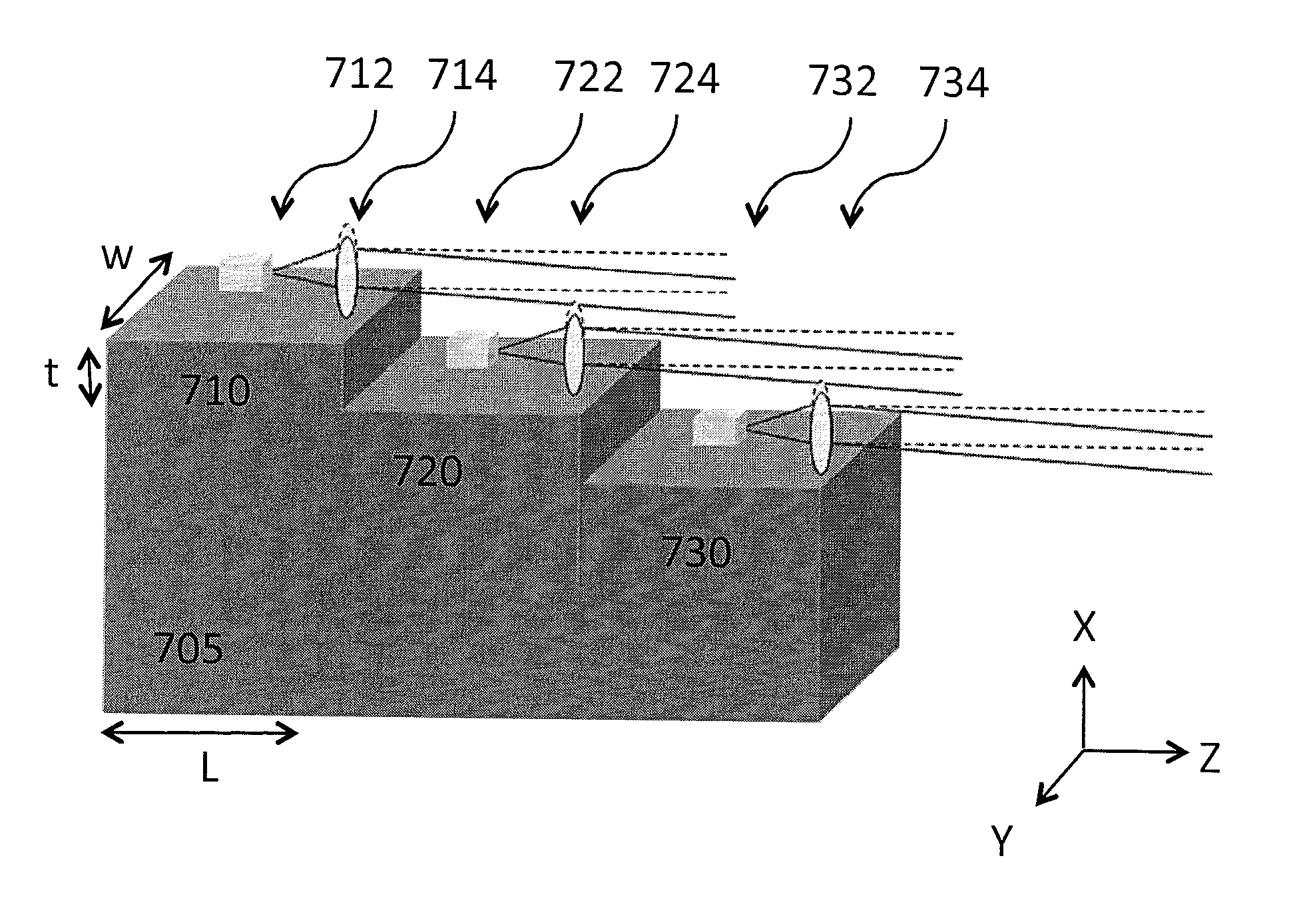
[0035]The instant invention relates to spatial-multiplexed multi-emitter pumps. In one embodiment, the laser diode emitters are stacked in a staircase formation to provide a spatially-multiplexed output wherein the pump includes a tilted collimated output beam that allows a variable number of emitters to be used inside packages having a same step height, while still attaining high coupling efficiency.

[0036]For a stack having a single row of emitters, the output power of the pump is determined by the number of diodes (N) times the coupling efficiency (CE). The CE is a function of the numerical aperture (NA) of the output fiber, the core diameter of the output fiber (e.g., which is determined by the application), combined beam size (h), and beam clipping (e.g., which is function of step height (t)). By decreasing step height (t), more emitters can be combined, but beam clipping increases. Accordingly, CE is function of the number of emitters and the step height for a given output fibe...


PUM


Abstract

Multi-mode diode emitters are stacked in a staircase formation to provide a spatially-mulitplexed output. Improved coupling efficiency is achieved by providing tilted collimated output beams that determine an effective step height of the stepped structure. Since the effective step height is dependent on the tilt angle, a variable number of emitters can be used inside packages having a same physical step height, while still attaining high coupling efficiency.

Description

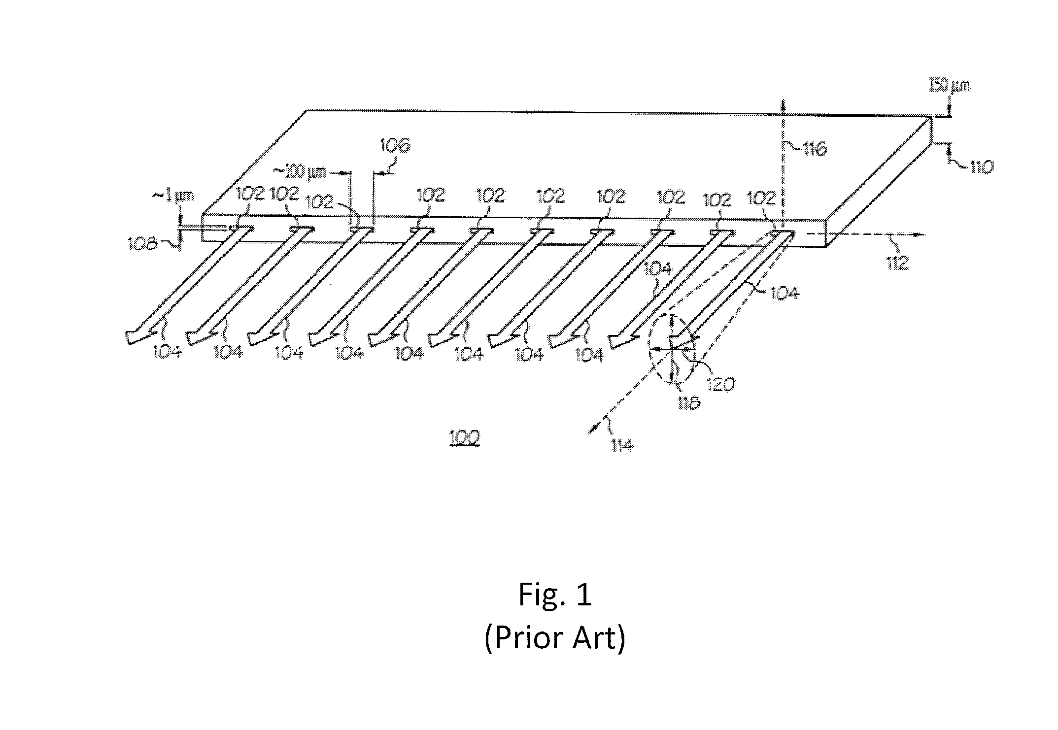
CROSS-REFERENCE TO RELATED APPLICATIONS[0001]Not Applicable.MICROFICHE APPENDIX[0002]Not Applicable.TECHNICAL FIELD[0003]The present application relates generally to laser diode arrays and in particular to high-brightness spatial-multiplexed multi-emitter pumps with tilted collimated beams.BACKGROUND OF THE INVENTION[0004]Laser diodes are used in many applications including materials processing, medical devices, telecommunications, printing, etc. In many of these applications, and in particular those in which laser diodes are used to optically excite or “pump” the gain media of other lasers, the laser diodes are aligned along a common substrate at regular intervals to form a row or strip of diode emitters. These laser diode bars provide a relatively high brightness.[0005]For example, referring to FIG. 1, there is shown a perspective view of a prior art laser diode bar 100. In this example, the diode bar includes ten diode emitters 102. Each diode bar typically has a width 110 that i...

Claims


Application Information

Patent Timeline
Patent Type & Authority Applications(United States)
IPC IPC(8): H01S5/022
CPCH01S5/005H01S5/4043H01S5/4012H01S5/02252H01S5/02326
Inventor GUO, JAMES YONGHONGSKIDMORE, JAY A.XU, LEICHENG, JANE
Owner LUMENTUM OPERATIONS LLC
Learn More