Method and device for manufacturing vitreous slag

a technology of vitreous slag and solidification method, which is applied in the field of dry solidification of slag, can solve the problems of dust and energy leaving the system, substantial thermal energy in the slag, and loss of heat recovery from the system, etc., and achieves excellent insulation properties, low thermal conductivity of the slag, and prevent dust and energy from leaving the system

Inactive Publication Date: 2013-06-20
PAUL WURTH SA
View PDF0 Cites 5 Cited by
  • Summary
  • Abstract
  • Description
  • Claims
  • Application Information

AI Technical Summary

Benefits of technology

[0057]Once the heat exchanger subunit is filled up, the slag particles inlet and the slag particles outlet port are sealed and the subunit is reconnected to the cooling gas stream while another heat exchanger subunit may be disconnected. The cooling gas flow through these heat exchanger subunits does thus not encounter any leakage, therefore preventing dust and energy leaving the system. The heat exchanger subunits

Problems solved by technology

In general, the slag has limited economic value.
Only a small part of the slag is used as a building material and a major part may have to be dumped as a waste material, although it contains substantial thermal energy, and is lost for t

Method used


Image

  • Method and device for manufacturing vitreous slag
  • Method and device for manufacturing vitreous slag
  • Method and device for manufacturing vitreous slag

Examples


Embodiment Construction

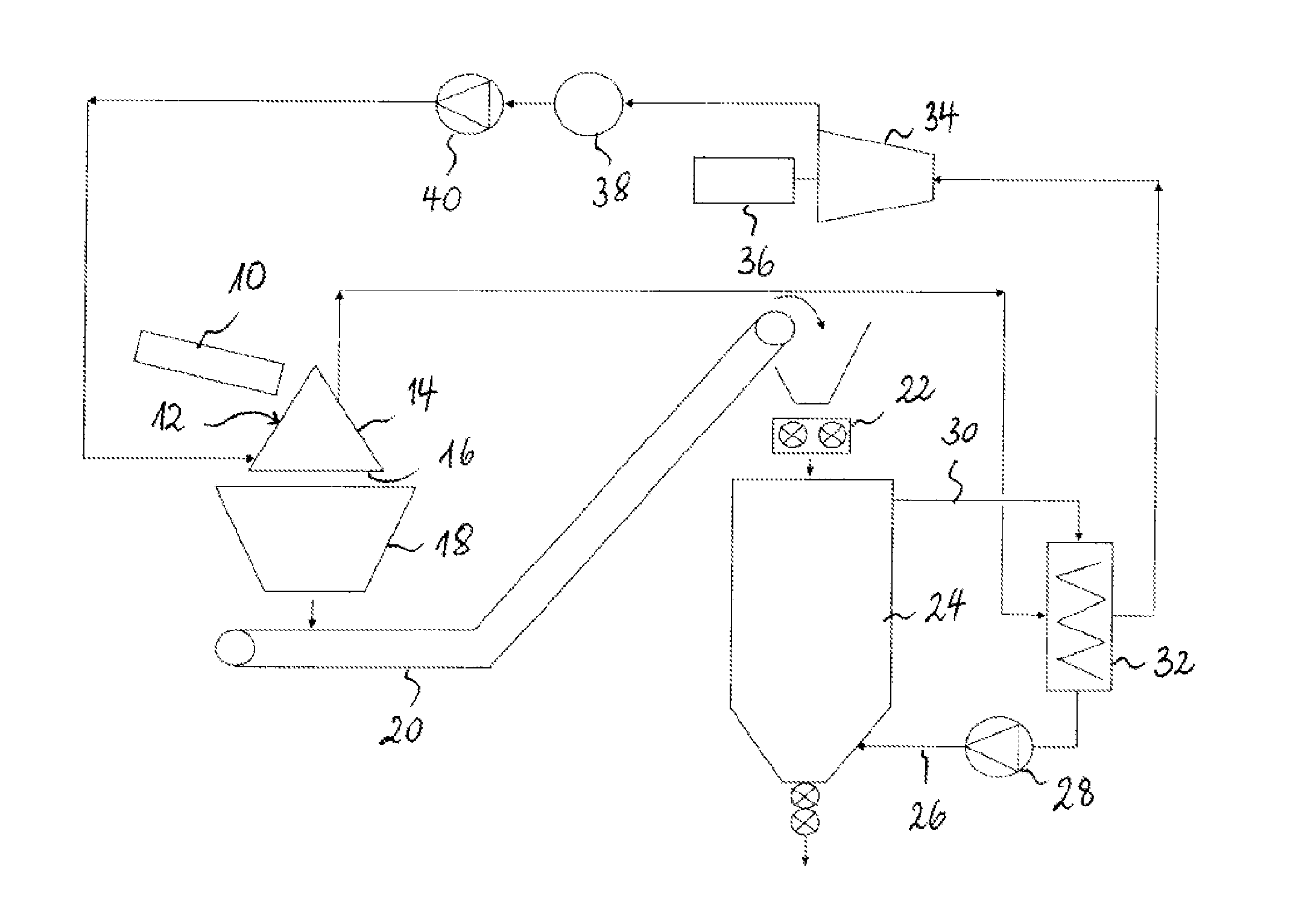
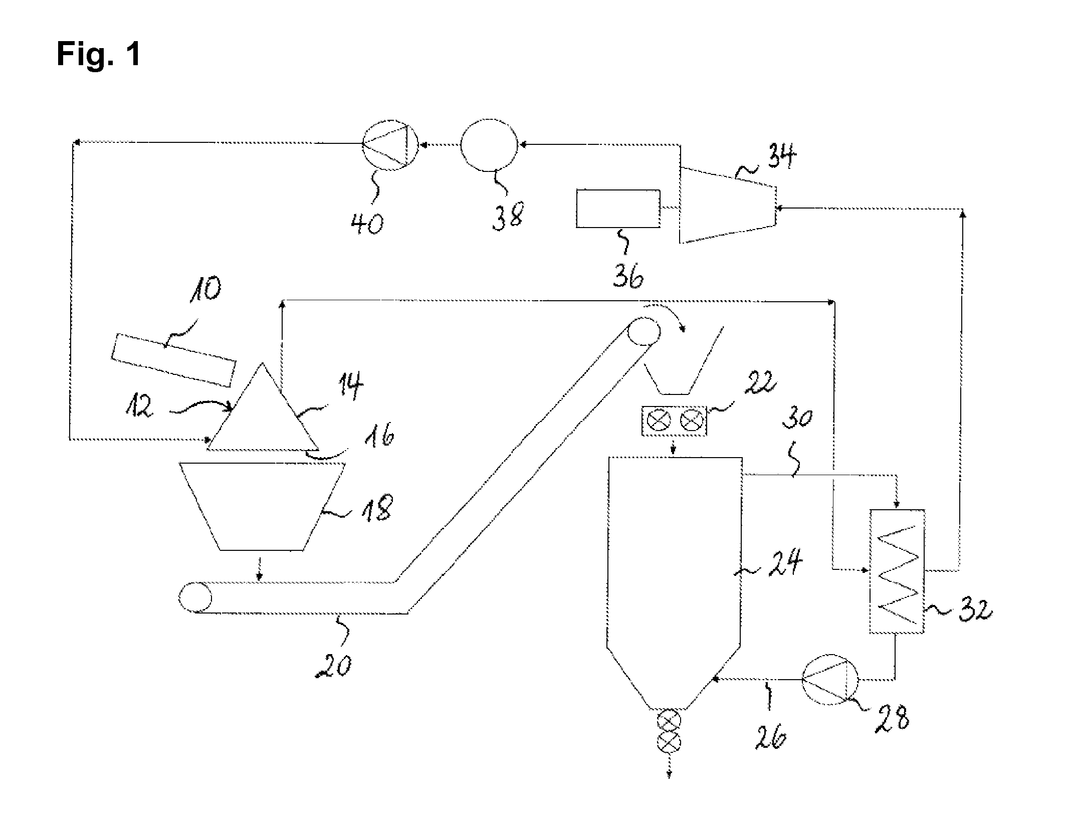
[0065]FIG. 1 schematically shows an installation for recuperating heat from slag comprising a rotary-cone vitreous slag manufacturing device according to a preferred embodiment of the present invention. As can be seen on FIG. 1, the liquid slag is poured from a slag runner 10 onto the outer surface 12 of a conical slag cooler 14. The liquid slag is poured onto the outer surface 12 of the cooler in one delimited zone and spreads over the entire length of the surface i.e. from the pouring zone substantially to the base 16 of the cone through the action of gravity. The liquid slag runs along the inclined surface of the slag cooler 14, forms a thin film on the surface of said cone and solidifies as it spreads over the cone. Owing to the rotation of the cone, the slag forms a solidified film substantially along the major part, such as e.g. 70% to 95%, of the outer surface of the cone. During the rotation of the conical slag cooler, the film of slag formed on the surface of the cone rapid...


PUM

PropertyMeasurementUnit
Temperatureaaaaaaaaaa
Lengthaaaaaaaaaa

Abstract

A process for manufacturing a vitreous slag including
    • rotating a cone about a vertical cone axis, the cone including an external shell having a lateral surface;
    • cooling the lateral surface of the external shell;
    • pouring molten slag onto the lateral surface of the cone to form a film of slag by gravity, which is solidified as it is entrained in rotation by the cone about the cone axis; and
detaching pieces of the film from the lateral surface and removing solidified slag in the form of the pieces after the film has been entrained through between 0.6 and 0.9 revolutions of the cone, the molten slag being poured onto the lateral surface in a pouring zone and spreads to form a film over substantially the entire length of the lateral surface, preferably over between 75% and 95% of the length of the lateral surface.

Description

TECHNICAL FIELD[0001]The present invention generally relates to dry solidification of slag from the metal industry and more particularly from the iron industry, in particular in combination with a heat recovery.BRIEF DESCRIPTION OF RELATED ART[0002]Molten slag at high temperature is usually produced in the smelting of ores and in the fining or refining of raw metal. The tapping of the slag removes heat from the system at a high rate and the liquid slag is cooled and assumes a solid state in a relatively short time and can then be handled, although with some difficulty.[0003]In general, the slag has limited economic value. Only a small part of the slag is used as a building material and a major part may have to be dumped as a waste material, although it contains substantial thermal energy, and is lost for the recovery of the heat that has been removed from the system.[0004]As the recognition of minimizing waste and of the need to save energy has increased, numerous efforts have been ...

Claims


Application Information

Patent Timeline
IPC IPC(8): C04B5/00
CPCC04B5/00C21C2100/06C21B3/08C21B2400/072C21B2400/08C21B2400/026Y02P10/25C21B2400/066
Inventor FRIEDEN, ROMAINEBNER, BILLSCHORR, TOMDUNCAN, SCOTTPAUL, GEORGEKAPPES, HORST
Owner PAUL WURTH SA
Why Eureka
Try Eureka