Microchannel heat exchanger fin

a technology of heat exchanger and microchannel, which is applied in the field of microchannel heat exchanger fin and tube configuration, can solve the problems of retaining large quantities of moisture, water or condensate within the fin and tube structure, and reducing the thermo-hydraulic performance or effectiveness of the heat exchanger

Inactive Publication Date: 2013-06-20
CARRIER CORP
View PDF6 Cites 9 Cited by
  • Summary
  • Abstract
  • Description
  • Claims
  • Application Information

AI Technical Summary

Benefits of technology

[0004]According to another aspect of the invention, a heat exchanger includes a plurality of tubes, each tube configured for a flow of fluid therethrough. One or more fins are located between adjacent tubes of the plurality of tubes. The one or more fins are spaced by a fin pitch (FP) and are configured to improve thermal energy transfer between the plurality of tubes and ambient air. Each fin includes a fin extension extending beyond a tube width. The extended portion of the fin is laterally flared and shaped to reduce capillary effects and enhance water drainage.

Problems solved by technology

Typical MCHX fin and tube arrangements, however, have the disadvantage of retaining large quantities of moisture, water or condensate, within the fin and tube structure, due to their high compactness and thus increased surface tension.
The accumulated moisture accelerates corrosion of the fin and tube structure which leads to decreased thermo-hydraulic performance or effectiveness of the heat exchanger and eventual failure of the heat exchanger when the tubes are corroded sufficiently to be perforated, thus releasing the cooling / heating fluid.
Further, along with retention of moisture, the typical structure leads to the buildup of corrodant substances and mechanical stresses in the structure leading to stress corrosion which further accelerates deterioration of the fin and tube structure and resultant failure of the heat exchanger.

Method used


Image

  • Microchannel heat exchanger fin
  • Microchannel heat exchanger fin
  • Microchannel heat exchanger fin

Examples


Embodiment Construction

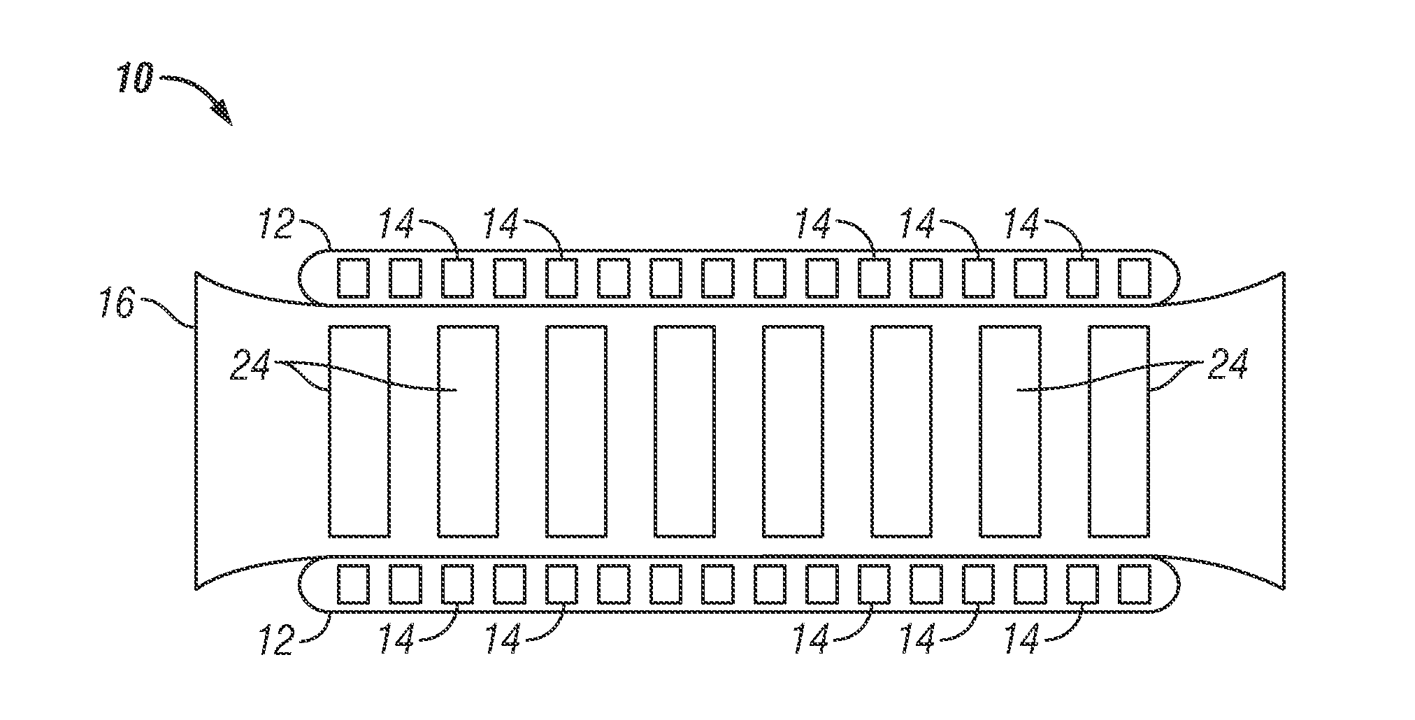
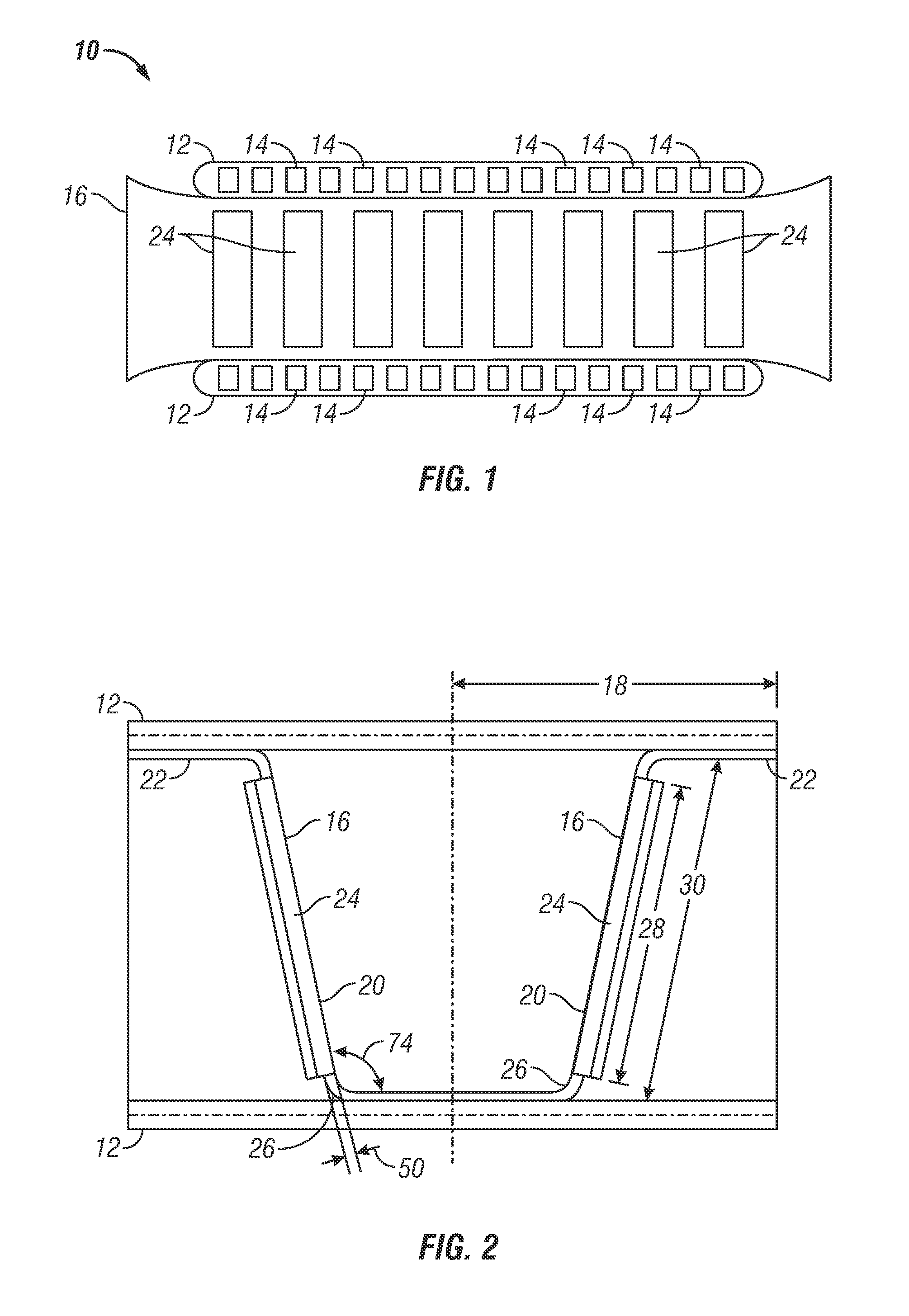
[0016]Shown in FIG. 1 is an embodiment of a tube and fin arrangement of a heat exchanger 10. The heat exchanger 10 includes a plurality of tubes 12. Each tube 12 in the embodiment shown includes multiple channels 14 through which cooling fluid is circulated. In the embodiment of FIG. 1, each tube includes sixteen channels 14, but it is to be appreciated that any number of channels 14 may be utilized. A plurality of fins 16 extend between the tubes 12 to aid in increasing heat transfer between the tubes 12 and the surrounding air. In some embodiments, the fins 16 are secured to the tubes 12 by, for example, brazing, or other suitable means such as for instance soldering or gluing, and in some embodiments, the fins 16 may have a fin thickness (FTH) of between about 50 and about 100 microns. It is to be appreciated that the fin thickness is merely exemplary, and other fin thicknesses outside of the described range may be utilized within the scope of the present disclosure. The heat exc...


PUM


Abstract

A heat exchanger includes a plurality of tubes (12), each tube configured for a flow of fluid therethrough and one or more fins located between adjacent tubes of the plurality of tubes. The one or more fins are spaced by a fin pitch (Fp,18) and are configured to improve thermal energy transfer between the plurality of tubes and ambient air. Each fin includes a fin face extending between the adjacent tubes, a substantially planar fin cap (22) connected to the fin face secured to one or the tubes, and a fin radius (Rc,26) connecting the fin face to the fin cap such that the fin radius is reduced to promote condensate removal from the heat exchanger.

Description

BACKGROUND OF THE INVENTION[0001]The subject matter disclosed herein relates to heat exchangers. More specifically, the subject disclosure relates to fin and tube configurations for microchannel heat exchangers.[0002]Heating, ventilation, air conditioning and refrigeration (HVAC & R) systems include heat exchangers to reject or accept heat between the refrigerant circulating within the system and surroundings. One type of the heat exchanger that has become increasingly popular, due to its compactness, structural rigidity and superior performance is a microchannel or minichannel heat exchanger (MCHX) which includes two or more containment forms, such as tubes, through which a cooling or heating fluid (such as refrigerant or glycol solution) is circulated. The tubes typically have a flattened cross-section and multiple parallel channels. Fins are typically arranged to extend between the tubes to aid in the transfer of thermal energy between the cooling / heating fluid and the surroundin...

Claims


Application Information

Patent Timeline
Patent Type & Authority Applications(United States)
IPC IPC(8): F28F1/12
CPCF28F1/022F28F1/128F28F1/12F28F17/005F28F2260/00F28F3/027
Inventor TARAS, MICHAEL F.JOARDAR, ARINDOMESFORMES, JACK LEONMEHENDALE, SUNIL S.
Owner CARRIER CORP
Why Eureka
Try Eureka