
Variable length vehicle stabiliser and vehicle with the variable length stabiliser

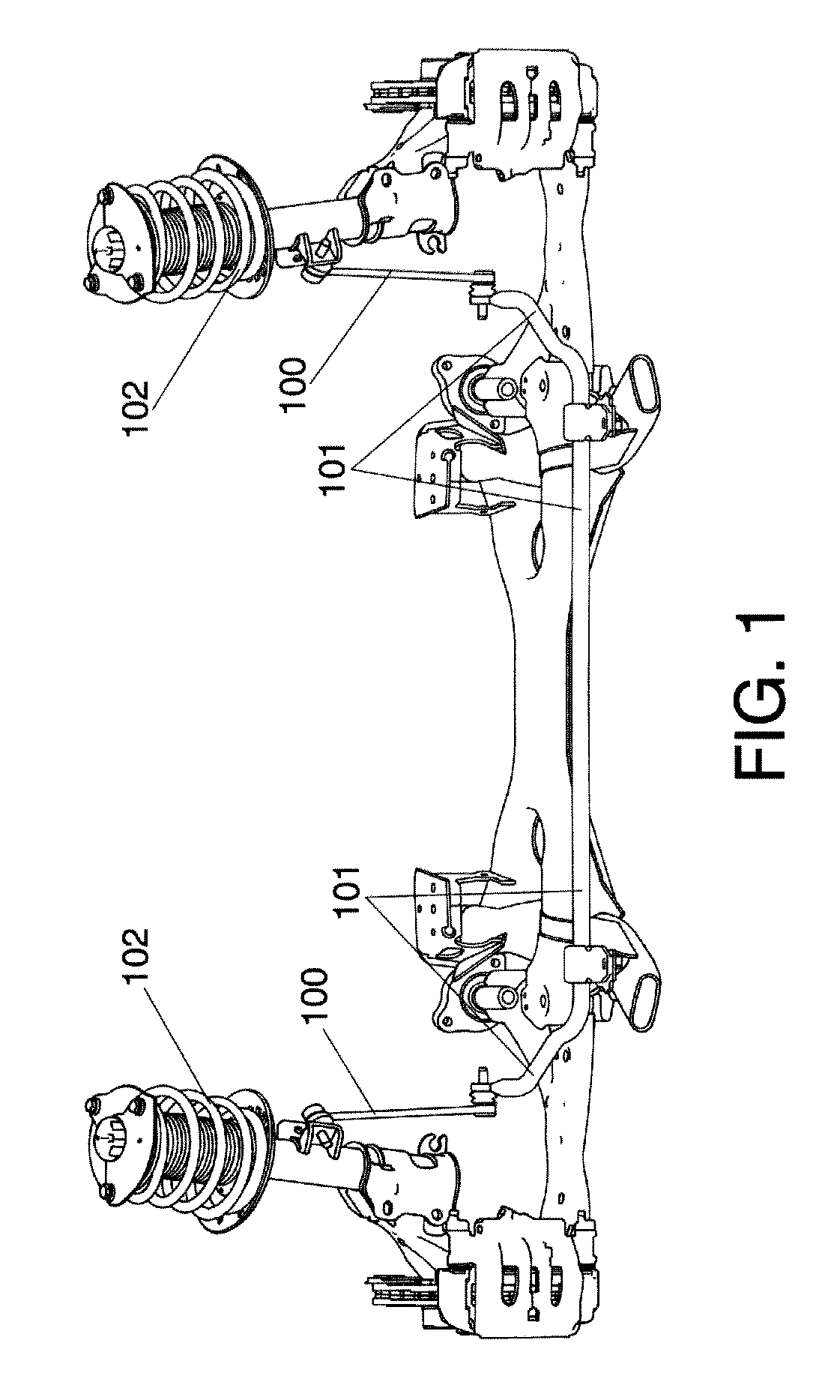
a vehicle stabiliser and variable length technology, applied in the direction of resilient suspensions, interconnection systems, transportation items, etc., can solve the problems of implying a fairly high energy consumption and requiring a large volum

Inactive Publication Date: 2013-06-20
EDAI TECHN UNIT A I E
View PDF13 Cites 8 Cited by
  • Summary
  • Abstract
  • Description
  • Claims
  • Application Information

AI Technical Summary

Benefits of technology

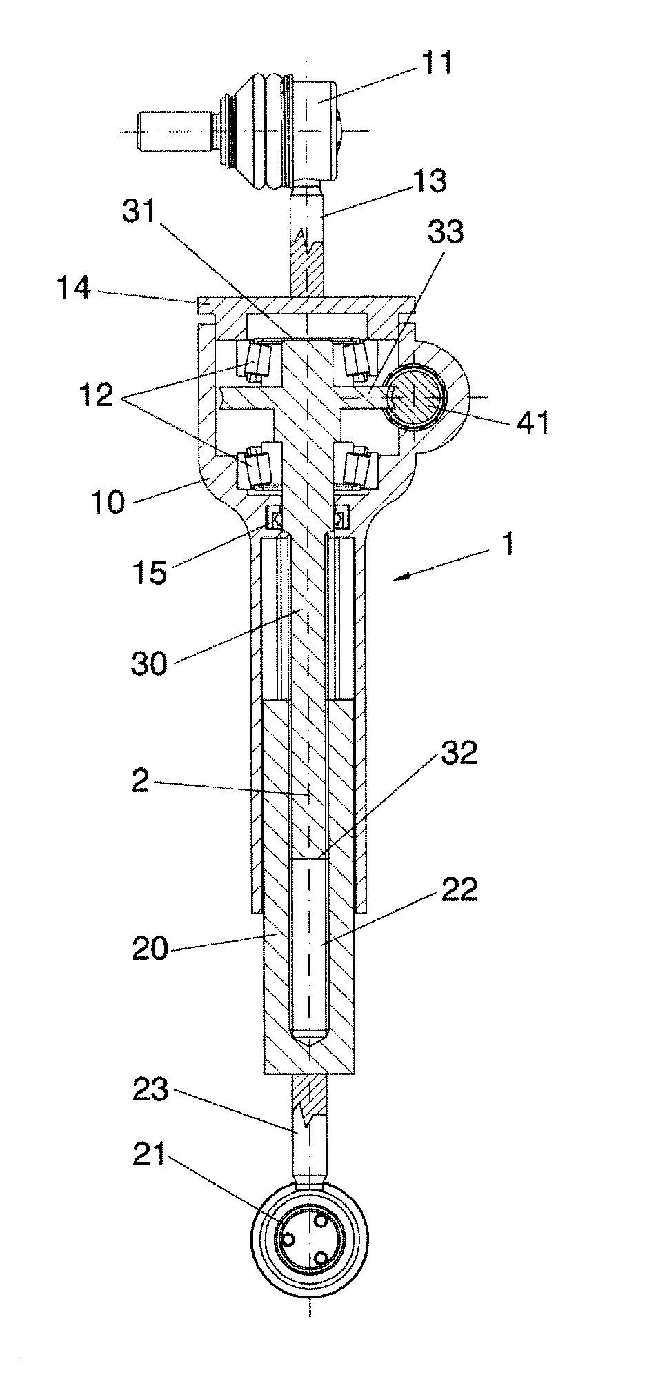
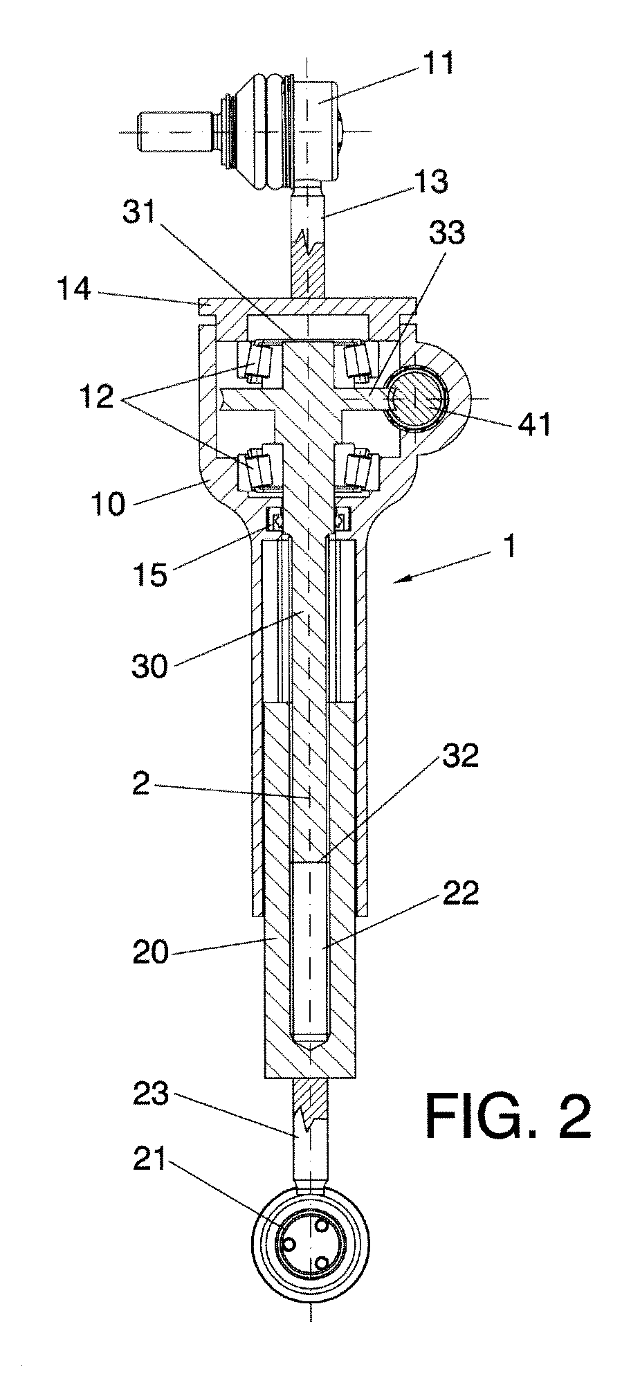
The invention is a device that prevents a stabilizer from transmitting torque to the coupling means of the stabilizer when it is not possible to rotate between them. This reduces the size of the device and allows for better stability. The device uses a threaded element and a smaller-diameter part to connect to the inner member, which helps to minimize the assembly diameter. Connecting the motor to the threaded element at a larger-diameter part allows for an additional reduction phase, which can reduce the power needed and allow for the use of a smaller motor.

Problems solved by technology

When the vehicle enters a curve, a centrifugal force is generated causing the body to tilt towards the outside of said curve, causing a roll moment.
US-A-2006 / 0113734 describes an example of a variable length stabiliser with a motor coupled at the end of a threaded rod, However, this configuration implies that a rotational force is transmitted to the means or devices for connecting or coupling the stabiliser to the rest of the vehicle (these means or devices are usually ball joints or the like), which can give rise to damage or wear.
On the other hand, the impact loads experienced by the mechanism directly affect the motor, which can also cause damage.
On the other hand, the motor is directly connected to the threaded rod, without reduction, so a relatively powerful motor is necessary, which can imply a fairly high energy consumption, larger volume, heavier weight and higher cost.
On the other hand, in the unit which moves along the threaded rod there is an intermediate element which absorbs part of the rotation of the threaded rod and makes control more difficult.
However, the arrangement of the rack bar inside the casing implies a certain risk of misalignment between the components.
Furthermore, although the rack and pinion system has its advantages, it implies limited reduction which can require an additional reduction phase or the use of a more powerful motor, which in turn implies drawbacks in terms of the volume and weight of the mechanism, and in terms of the cost.

Method used


Image

  • Variable length vehicle stabiliser and vehicle with the variable length stabiliser
  • Variable length vehicle stabiliser and vehicle with the variable length stabiliser
  • Variable length vehicle stabiliser and vehicle with the variable length stabiliser

Examples


Embodiment Construction

[0012]The invention relates to a stabiliser which changes the length between kinematic centres by means of actuating a motor. This allows controlling the torque transmitted by the stabiliser bar, being able to make it more or less rigid depending on the type of drive desired.

[0013]A first aspect of the invention relates to a vehicle stabiliser (and more specifically for linking the stabiliser bar to the suspension of a wheel or the like), comprising a telescopic assembly with a longitudinal axis comprising an outer member and an inner member arranged at least partially inside the outer member and axially movable with respect to the outer member according to said longitudinal axis, without the possibility of rotating. The stabiliser comprises first coupling means (for example, a ball joint or the like) for coupling the stabiliser to a part of the vehicle, and second coupling means for coupling the stabiliser to another part of the vehicle as is conventional. The first coupling means ...


PUM


Abstract

The stabiliser comprises a telescopic assembly (1) with an outer member (10) and an inner member (20) axially movable with respect to the outer member, without the possibility of rotating. A threaded element (30) is coupled to the outer member (10) and to the inner member (20) such that when said threaded element (30) rotates an axial movement of said inner member (20) with respect to said outer member (10) occurs, varying the length between kinematic centres of the stabiliser.

Description

TECHNICAL FIELD OF THE INVENTION[0001]The invention is comprised in the field of automotive vehicle stabilisers, and more precisely in the field of variable length stabilisers.BACKGROUND OF THE INVENTION[0002]The stabiliser is a part linking the stabiliser bar with the suspension of a wheel. Stabilisers belong to the kinematic chain usually formed by the stabiliser bar, stabiliser, suspension and vehicle chassis. The stabiliser is the element responsible for transmitting the stresses generated by the stabiliser bar to the suspension of a wheel, and vice versa, generating in the vehicle chassis a moment opposite the roll moment of the vehicle, achieving greater lateral rigidity of the vehicle.[0003]When the vehicle enters a curve, a centrifugal force is generated causing the body to tilt towards the outside of said curve, causing a roll moment. At the same time, the stabiliser bar attached to the suspension of a wheel by means of the stabiliser experiences torsion causing a moment op...

Claims


Application Information

Patent Timeline
IPC IPC(8): B60G17/00
CPCB60G17/0162B60G17/00B60G2204/1224B60G21/0558
Inventor TEIJEIRO CASTRO, RAFAELSERAS ESCOLANO, IVAN
Owner EDAI TECHN UNIT A I E
Learn More