Antenna testing enclosures and methods for testing antenna systems therewith

a technology for antenna systems and enclosures, applied in the field of antennas, can solve the problems of limited phase difference measurement in conventional systems, and achieve the effects of improving system testing accuracy, cost saving, and improving isolation

Inactive Publication Date: 2013-06-20
L 3 COMM INTEGRATED SYST
View PDF17 Cites 32 Cited by
  • Summary
  • Abstract
  • Description
  • Claims
  • Application Information

AI Technical Summary

Benefits of technology

[0005]Disclosed herein are antenna testing enclosures (e.g., antenna hoods) that may be employed to provide improved isolation from background ground radio noise and improved system testing accuracy that is not possible with conventional antenna testing hoods and systems. The disclosed testing enclosures may be advantageously employed to achieve cost savings by providing visibility to the RF signal path for troubleshooting and system checks that otherwise may only be accomplished in a pristine environment with substantially no background ground ambient noise and with substantially no reflections, e.g., such as the pristine RF environment existing during flight tests of aircraft-based antenna systems. In one exemplary embodiment, the disclosed testing enclosures may be implemented for ground testing one or more antennas and signal paths of an aircraft signal receiving system (e.g., for DF antenna systems) to identify hardware discrepancies without requiring the additional time and cost of an aircraft recalibration flight. Significant time savings over conventional methodology may be realized in one embodiment when using the disclosed testing enclosures for end to end precision RF path testing and for verifying one or more electrical properties such as amplitude / gain and phase of multiple antennas installed as an array on an aircraft such as an aircraft-based DF system.
[0006]Examples of applications for the disclosed testing enclosures include, but are not limited to, testing during development and initial deployment and installation of antenna systems, field testing of previously installed antenna systems as a part of periodic antenna system maintenance operations, verification of proper operation of antenna systems after they have been disturbed to facilitate repairs, etc. In one embodiment, improved visibility and system stability may be made possible with the disclosed antenna testing enclosures and testing systems thereof, allowing antenna systems (e.g., DF antenna array systems such as DF interferometer, other phased array antenna systems, traffic collision avoidance system “TCAS” antenna systems, GPS antenna systems, etc.) to be tested and stabilized prior to initial flight tests, and allowing troubleshooting of antenna systems more effectively in the event that failures occur. Such characteristics may be taken advantage of, for example, to allow for test flights of newly installed aircraft antenna arrays on an aircraft to roll directly into a calibration flight, providing significant schedule savings since antenna and RF signal path problems may be discovered prior to the initial flight and not afterwards.
[0007]In one exemplary embodiment, multiple antenna testing enclosures may be provided in the form of a RF test system of multiple individual antenna enclosures that are configured for installation over respective multiple individual antennas of an antenna array, such as an aircraft-mounted DF system antenna array. In such an embodiment, the disclosed antenna enclosure apparatus may be used to verify integrity of the RF signal path, amplitude and / or phase of the antennas of the array and the DF system electronics installed on the aircraft when the aircraft is parked on the ground. In this regard, the RF test system may be employed in one exemplary embodiment to allow simultaneous, substantially uniform amplitude and substantially equal phase injection of RF energy into each antenna in the DF system antenna array, to verify the complete RF path from each antenna to the DF receiver, to isolate and reduce interference with the test measurements from external AC and ground effects, and to provide a test environment required for precise measurements of the DF system and its antenna array. Advantageously, the disclosed RF test system and its multiple antenna disclosures may be so used to verify the amplitude and phase of a DF system installed on an aircraft without requiring expensive and time consuming flight testing operations.

Problems solved by technology

Such conventional systems are limited to measuring phase differences of 10 degrees or more between the multiple antennas.

Method used


Image

  • Antenna testing enclosures and methods for testing antenna systems therewith
  • Antenna testing enclosures and methods for testing antenna systems therewith
  • Antenna testing enclosures and methods for testing antenna systems therewith

Examples


Embodiment Construction

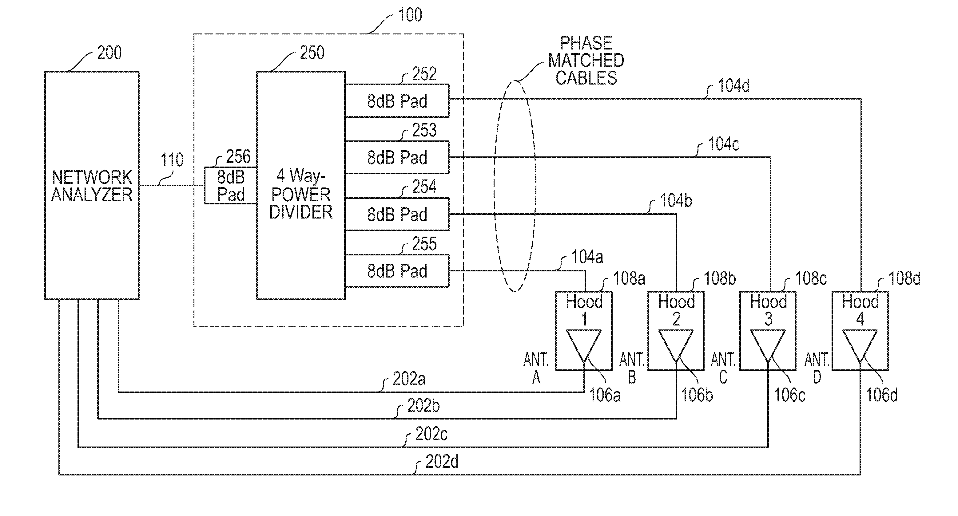
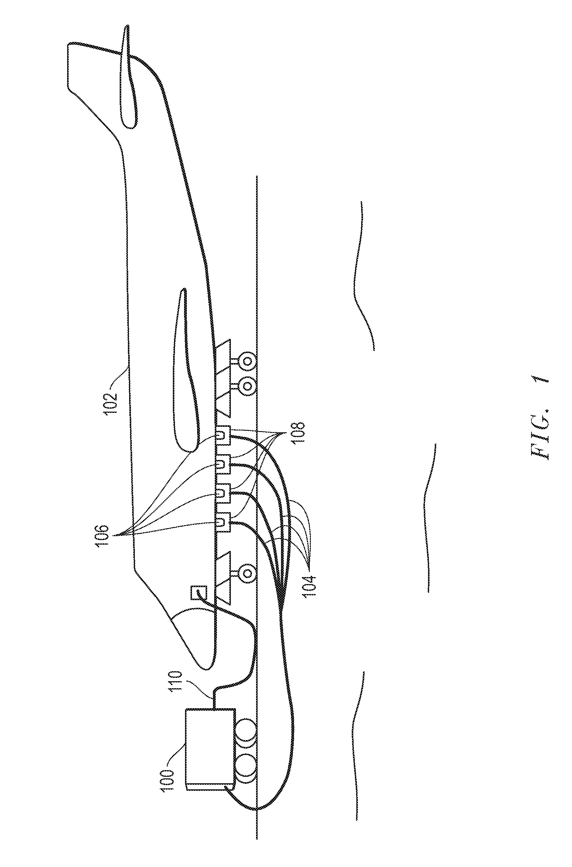
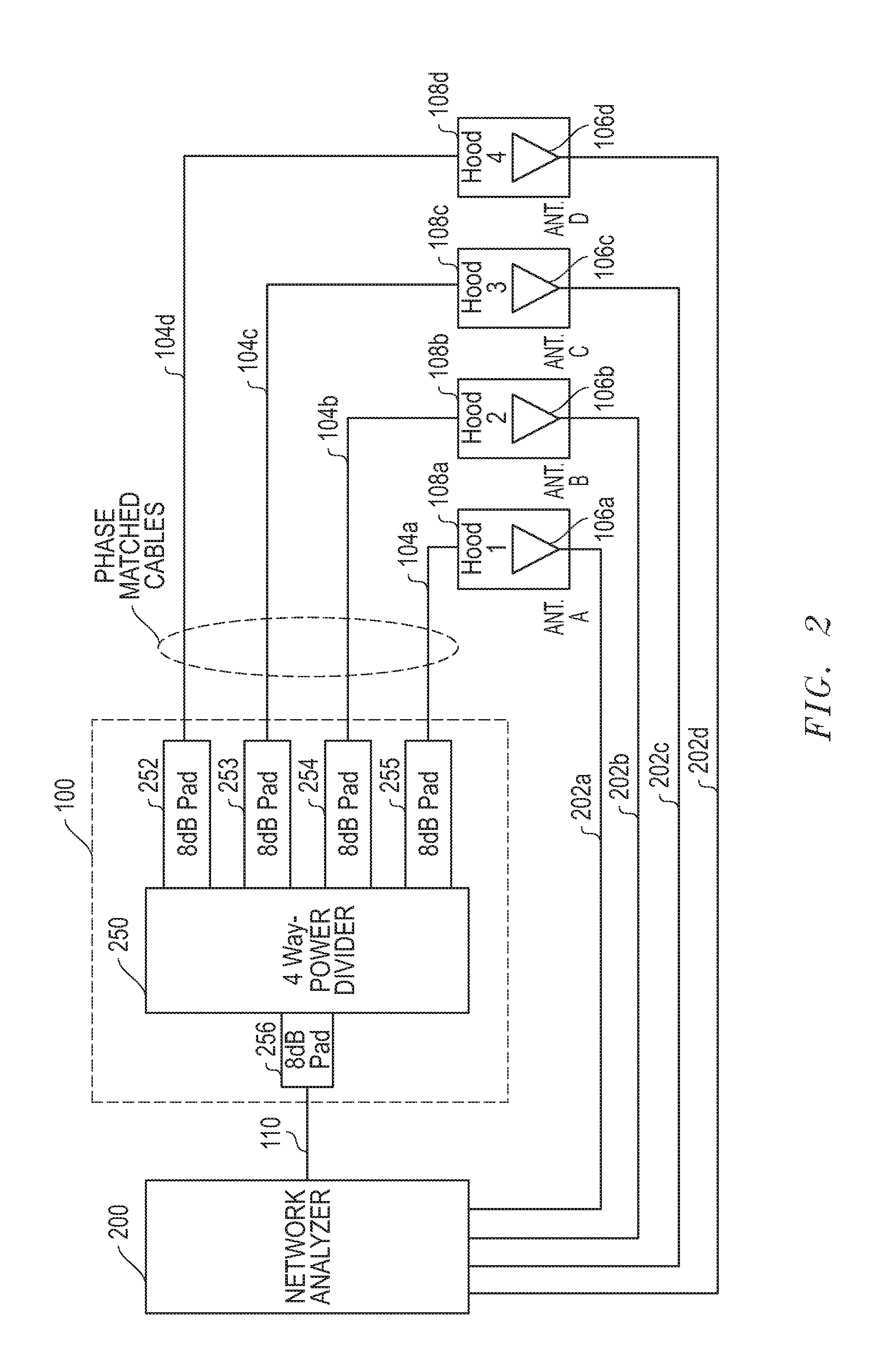
[0023]FIG. 1 illustrates an aircraft 102 (e.g., manned aircraft, unmanned drone, etc.) configured with a DF receiver system that includes an array of multiple external antennas 106 that are configured to receive and locate a radio frequency (RF) signal while aircraft 102 is airborne. In this embodiment, each of antennas 106 are blade antennas, such as a Dayton Granger DG 720032 or a Chelton Microwave 11D28500 blade antenna. However, it will be understood that the disclosed apparatus, systems and methods may be employed with other types of antennas and / or may be employed with single antennas rather than multiple antennas of an antenna array. Moreover, it will also be understood that the disclosed apparatus, systems and methods may be employed with one or more antennas mounted on or otherwise provided on mobile or stationary platforms other than a fixed wing aircraft, e.g., such as a helicopter, building, cell or other type of antenna tower, truck, ship, submarine, etc.

[0024]As shown ...


PUM


Abstract

Antenna enclosure apparatus are provided that may be used to verify the signal path integrity, amplitude and / or phase of a single antenna or multiple antennas of direction finding (DF) antenna array and associated electronics without interference of external signals such as ground interference signals present when an aircraft-based antenna is tested on the ground. An individual antenna test enclosure may in one embodiment be provided as an antenna hood having a cavity dimensioned for internally receiving an antenna, such as an aircraft external blade antenna. The cavity of the antenna enclosure may be lined with a RF absorbing material inside the enclosure to allow for RF path testing with substantially no “ringing”, so that accurate phase and gain testing of a received antenna and its RF signal path may be accomplished.

Description

[0001]This invention was made with United States Government support under Contract No. FA8620-06-G-4003. The Government has certain rights in this invention.FIELD OF THE INVENTION[0002]This invention relates generally to antennas, and more particularly to antenna testing enclosures and methods for testing antenna systems therewith.BACKGROUND[0003]Aircraft are provided with external antennas for a number of applications. These antennas are coupled by a radio frequency (RF) signal path to receive or transmission circuitry within the aircraft. In the past, the RF signal receive path of such an aircraft have been tested on the ground by removing the antennas and injecting a test signal into the RF cables of the signal path. In other cases, a signal-radiating antenna element has been directly taped against the surface of an aircraft receive antenna for applying a test signal to the antenna and its signal path.[0004]In yet other cases, antenna hoods have been employed to enclose and groun...

Claims


Application Information

Patent Timeline
Patent Type & Authority Applications(United States)
IPC IPC(8): G01R29/08
CPCG01S3/023
Inventor HEIN, PAUL W.LULE, EDWARD K.PITTS, JR., JAMES L.FOX, DENNIS M.
Owner L 3 COMM INTEGRATED SYST
Why Eureka
Try Eureka