System and method for increasing a feedback detection rate in an audio system

Inactive Publication Date: 2013-06-20
MUSIC GROUP IP
View PDF1 Cites 8 Cited by
  • Summary
  • Abstract
  • Description
  • Claims
  • Application Information

AI Technical Summary

Benefits of technology

The present invention provides a way to quickly detect and remove feedback in an audio system that occurs quickly. This helps to improve the overall quality of the audio signal.

Problems solved by technology

When a system gains increase very quickly, feedback may occur abruptly, and the noise can be substantial.

Method used


Image

  • System and method for increasing a feedback detection rate in an audio system
  • System and method for increasing a feedback detection rate in an audio system
  • System and method for increasing a feedback detection rate in an audio system

Examples


Embodiment Construction

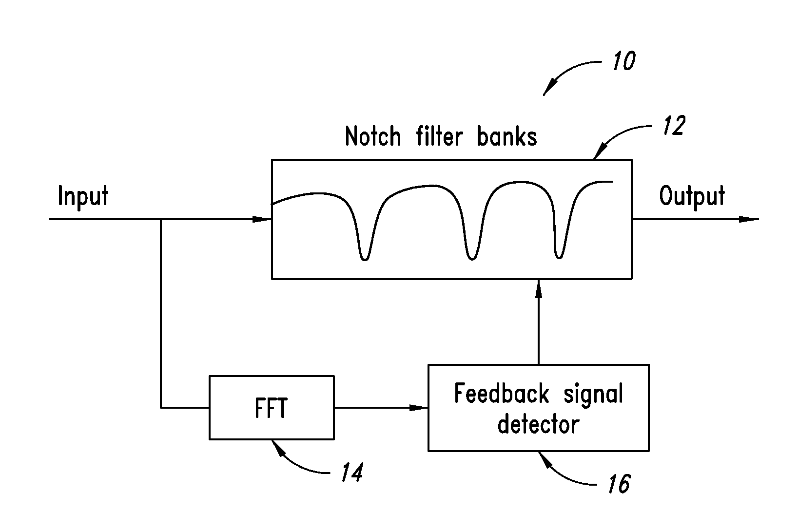
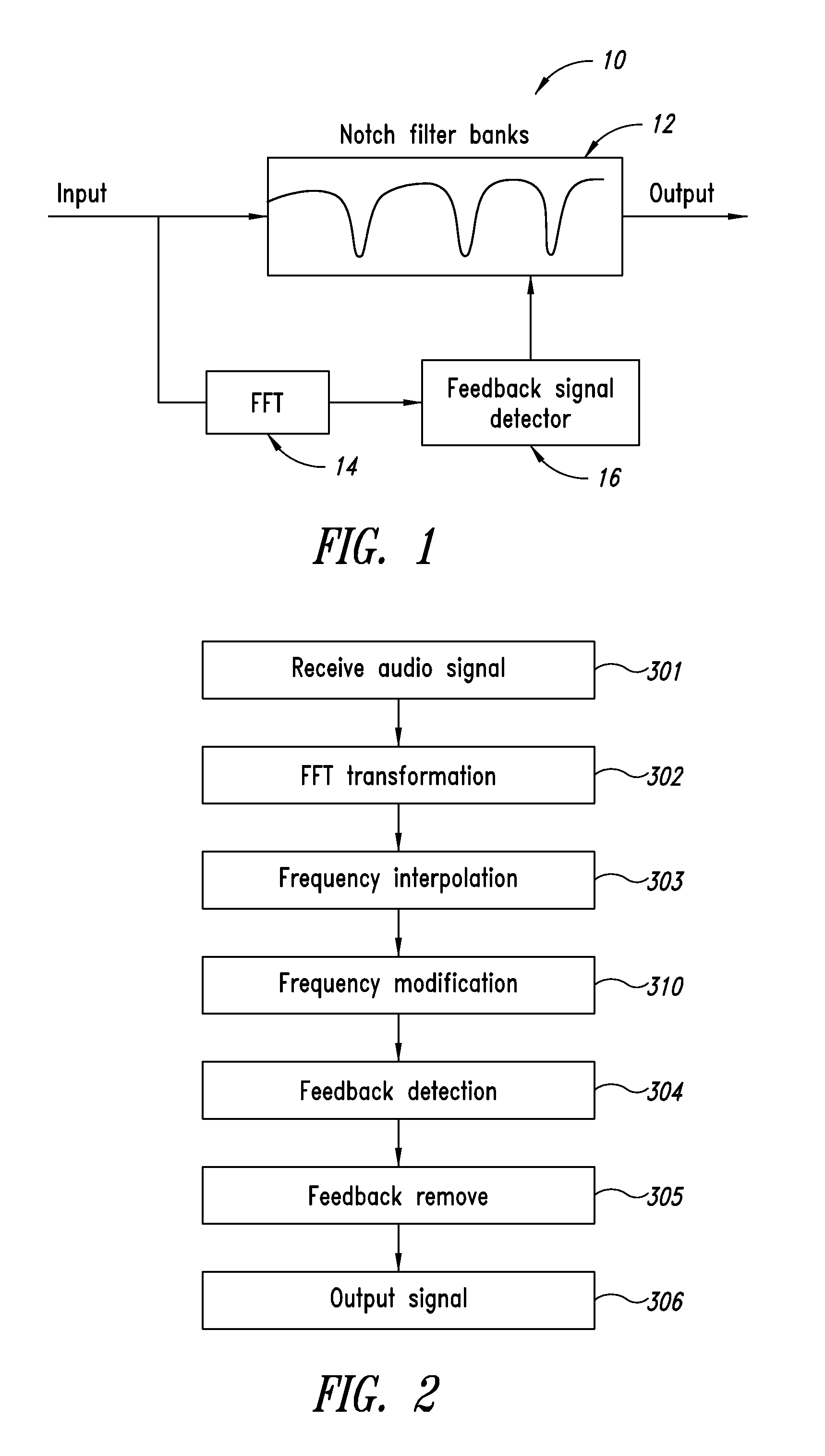
[0013]The present disclosure provides a system and method for removing feedback noise in an audio system, and more particularly, in a public announcement system that utilizes a microphone. This system includes an analyzing unit, which may utilize FFT processing and Feedback signal detection, and an adaptive feedback cancellation unit for removing the feedback noise, which may include, for example, 36 IIR notch filters for one channel. One exemplary embodiment of a system 10 formed in accordance with the present disclosure is illustrated in FIG. 1. The system 10 includes an input coupled to a bank of notch filters 12 and in parallel to a Fast Fourier Transform (FFT) block 14. The FFT block 14 has an output coupled to an input of a Feedback signal detector 16 that in turn has an output coupled to the Notch filter bank 12, the output of which forms the output for the system.

[0014]FIG. 2 illustrates one embodiment of a flowchart for a frequency removal process in accordance with the met...


PUM


Abstract

A system and method for removing feedback noise in an audio system includes an analyzing unit, which may utilize FFT processing and Feedback signal detection, and an adaptive feedback cancellation unit for removing the feedback noise, which may include, for example, 36 MR notch filters for one channel. A method to detect feedback noise in a substantially short amount of time combines increasing signal characteristics with full scale characteristics to find the feedback signal in a limited amount of time.

Description

BACKGROUND[0001]1. Technical Field[0002]The present disclosure relates in general to feedback detection and elimination in an audio system and, more particularly, to a system and method for rapid feedback detection and elimination.[0003]2. Description of the Related Art[0004]In the amplification and broadcast of music or other performances, the total content of the broadcast audio signal can be distorted by frequency attenuation, the characteristics of a room, the speaker system or other factor. In general, audio amplification systems use a manual equalizer to compensate the undesired frequency characteristics. The operator can adjust the gain of the frequency band using, for example, a slider attenuator in an equalizer.[0005]Current systems may also contain automatic equalizers which monitor the input signal in real time and set the corresponding equalizer parameters for feedback noise. In these systems, the magnitude of one frequency band in the input signal is typically compared ...

Claims


Application Information

Patent Timeline
IPC IPC(8): H04B15/00
CPCH04R3/02H04B15/00H04R27/00
Inventor HUANG, TIAN QIAN
Owner MUSIC GROUP IP
Why Eureka
Try Eureka