Device and method for measuring pressure exerted on a surface

a pressure measurement and surface technology, applied in the field of devices and methods, can solve the problems of no reliable method of ensuring continence, no device to accurately determine the magnitude of pressure required to achieve continence, and rudimentary methods for assessing and treating stress incontinence, etc., to achieve the effect of reducing the risk of bed sores

Active Publication Date: 2013-06-20
THE BOARD OF TRUSTEES OF THE UNIV OF ILLINOIS
View PDF3 Cites 3 Cited by
  • Summary
  • Abstract
  • Description
  • Claims
  • Application Information

AI Technical Summary

Benefits of technology

[0011]The pressure sensor is capable of connecting to other surfaces, besides a glove. For example, one or more pressure sensors may be connected to a sterile cover or blanket used to determine pressure in a wide range of medical applications. For example, anesthetized, or otherwise unconscious or uncommunicative patients cannot warn medical personal about uncomfortable pressure points that may have a deleterious effect on the body. Accordingly, the devices and methods provided herein are compatible for use in other applications, including “passive” applications where the patient is the person responsible for the force that is being monitored in real-time. Above a certain threshold level, the device may alarm to indicate to medical personal that corrective action should be taken. This can be of particular use in a rehabilitation setting, where the patient may be confined to bed for relatively long periods of time, and such a pressure sensor system and method used to minimize risk of bed sores. In another aspect, the sensor may be an implantable surface affixed to a surface of a medical device that is implanted into a patient. In this aspect, the sensor may remain in the patient along with the implanted device.

Problems solved by technology

With respect to an application for treating urinary stress incontinence, conventional methods for assessing and treating stress incontinence are rudimentary and suffer serious drawbacks.
Those methods, however, do not use a device to accurately determine the magnitude of pressure required to attain continence.
This means that the surgeon has no reliable method for ensuring the pressure exerted on the urethra by the structure corresponds to the pressure exerted pre-surgically that alleviated incontinence.
Serious complications can arise when the surgically-imparted force on the urethra is not appropriate to the minimum pressure required to alleviate incontinence.
If the pressure is too low, recurrent stress incontinence may occur, requiring additional invasive intervention.
If the pressure is too high, the sling may prematurely erode and there may be an increased risk of infection, which may require, again, additional surgical intervention.

Method used


Image

  • Device and method for measuring pressure exerted on a surface
  • Device and method for measuring pressure exerted on a surface
  • Device and method for measuring pressure exerted on a surface

Examples


example 1

Device and Method Characterization

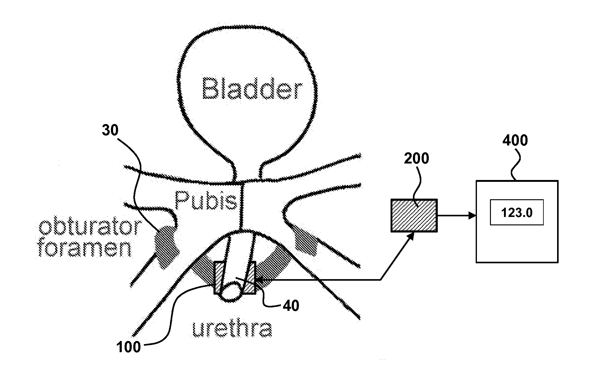
[0043]FIG. 3B illustrates placement of pressure sensor 100 between the sling 30 and urethra 40, along with the microcontroller 200 and display 400. Appropriate pressure or force generation on the urethra by the surgical intervention provides improved surgical outcome and reduces post-surgical complications. In this manner, real-time readout 400 of the pressure or force used to support the urethra is provided, thereby providing precise adjustment of sling 30 to obtain the desired supporting pressure or force on the urethra. In an aspect, the desired pressure is obtained presurgically (alleviation output), and is matched during surgery by varying the tension of the sling 30 to generate a pressure readout 400 that corresponds to the desired pressure (alleviation output).

[0044]The pressure sensor system 10 provided herein may have one or more pressure sensors and a drive circuit to accommodate the one or more sensors. In an aspect, the device comprises ...

example 2

Clinical Use

[0054]The device is optionally used in clinical and / or surgical procedures. Specifically, the minimum pressure required to prevent leaks are determined in a male and a female patient and intraoperative measures are obtained. Alternatively, the device is used for a non-surgical procedure.

[0055]Table 1 provides a summary of use of the device with six patients suffering urinary stress incontinence (3 male and 3 female). In a clinical setting, the pressure sensor device was used to quantify the amount of force required to stop leakage (as reflected in the last column “stop leakage measure”). Various other relevant parameters are summarized in the table. With this information, a sling is implanted with a generated pressure or force on the urethra measured by a pressure sensor that is equal to or substantially corresponds to the stop leakage measure obtained in the clinical setting. This process of measuring the pressure in the clinic provides a suitable range of pressures tha...

example 3

Pressure Sensor Incorporated into a Glove for Medical Procedures

[0056]The pressure sensor device and system is useful for a number of applications. For example, FIG. 11 illustrates pressure sensor(s) 100 connected to the fingertip of a glove 600. The sensor(s) 100 can be connected to an inner or to an outer surface of the glove. In an aspect, a single sensor is connected to the glove, such as at a glove fingertip corresponding to the index finger fingertip. Display 400 provides a real-time readout 410 of the pressure sensor output, such as a numerical voltage, numerical pressure, or numerical force by connection 420, which may be a wireless connection or a wired connection between the sensor and display. The sensor 100 is positioned so that it is between the portion of the hand or finger applying the force and the surface upon which the force is applied. In this fashion, a medical caregiver can easily and instantaneously have a quantitative measure of the force the caregiver is appl...


PUM


Abstract

Provided are methods and devices for measuring pressure exerted against a surface. In an aspect, the surface corresponds to the urethra and the device measures the pressure exerted against the urethra. Methods include treatment of a patient suffering urinary stress incontinence. A pressure sensor system is used to determine, pre-surgically, the minimum pressure required to alleviate incontinence. During surgery, the pressure sensor system is employed to ensure the surgical intervention provides a corresponding minimum pressure that was clinically identified. In this manner, the surgical intervention is precisely monitored and measured to insure the appropriate pressure is exerted on the urethra to alleviate stress incontinence, thereby improving surgical outcome and decreasing post-operative complications.

Description

CROSS-REFERENCE TO RELATED APPLICATIONS[0001]This application claims the benefit of U.S. provisional application 61 / 333,824 filed May 12, 2010, which is incorporated by reference in its entirety to the extent not inconsistent with the disclosure herein.BACKGROUND OF THE INVENTION[0002]Provided herein are various devices and methods that measure the pressure or force exerted against a surface. One application of the devices and methods provided herein are for surgical procedures that address urinary incontinence, including female stress incontinence.[0003]Urinary incontinence occurs in both men and women and is typically associated with unwanted urinary leakage that occurs with abdominal pressure increases such as from sneezing, coughing, hiccupping, exercise, laughing and other such stimuli. Interventions to address urinary incontinence include surgical procedures. Many procedures involve a surgical injection and placement of a material to mechanically support the bladder neck or th...

Claims


Application Information

Patent Timeline
Patent Type & Authority Applications(United States)
IPC IPC(8): A61F2/00A61B5/20
CPCA61B5/03A61F2/0045A61B5/20A61B5/0053A61B5/6852A61B5/686A61B2562/247A61B5/6885A61B5/205A61B5/4851A61B5/6806A61B2562/0247A61B5/6874
Inventor KOCJANCIC, ERVINNIEDERBERGER, CRAIG S.
Owner THE BOARD OF TRUSTEES OF THE UNIV OF ILLINOIS
Why Eureka
Try Eureka