Proppant placement

a proppant and placement technology, applied in the direction of fluid removal, chemistry apparatus and processes, borehole/well accessories, etc., can solve the problem of non-uniformity of the proppant pack

Inactive Publication Date: 2013-06-27
SCHLUMBERGER TECH CORP
View PDF7 Cites 109 Cited by
  • Summary
  • Abstract
  • Description
  • Claims
  • Application Information

AI Technical Summary

Benefits of technology

[0006]We have now found that a tight formation can be fractured successfully using a fine mesh solid of smaller size than has been conventionally recognized to be suitable for use as a proppant, combined with non-uniformity in the proppant pack.

Problems solved by technology

We have now found that a tight formation can be fractured successfully using a fine mesh solid of smaller size than has been conventionally recognized to be suitable for use as a proppant, combined with non-uniformity in the proppant pack.

Method used


Image

  • Proppant placement
  • Proppant placement
  • Proppant placement

Examples


example 1

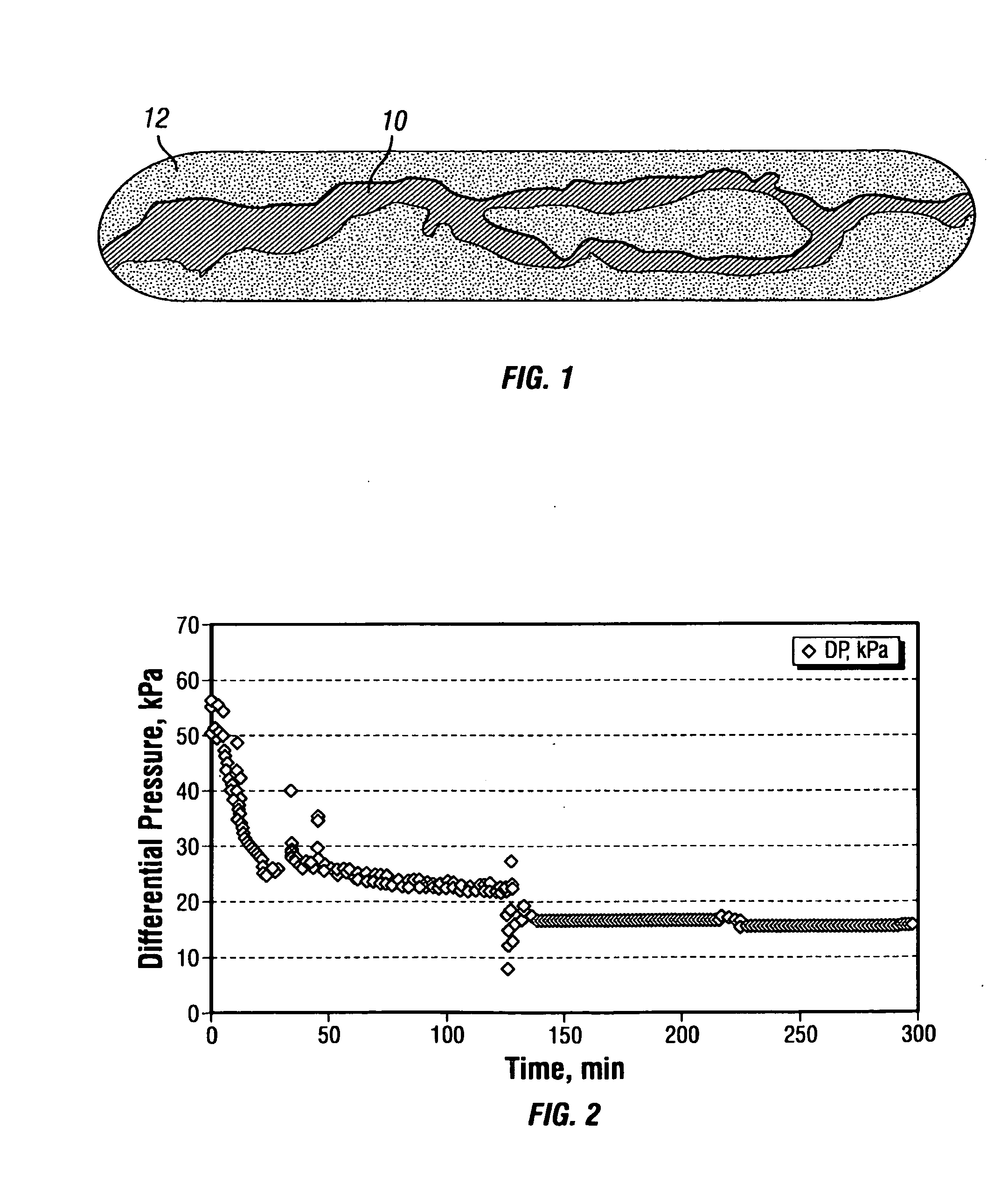
[0120]Hydraulic differential pressure was measured in a silica flour pack while pumping potassium chloride brine (2 wt %) at a flow rate of 0.5 ml / min. The silica flour comprised 99.5% quartz, measured by X-ray diffraction. The silica flour consisted of particulates less than 44 microns (325 US mesh) with median diameter of 18.4 microns. The loading comprised 4.9 kg / m2 (2.0 lb / ft) in an API recommended conductivity cell between two metal cores under closure stress of 13.8 MPa (2000 psi). FIG. 1 is a schematic drawing of a typical branched network channel 10 formed around an island in the silica flour pack 12 by washout in the conductivity cell. FIG. 2 shows a time-trace of the pressure drop in the silica flour pack and illustrates the slow equilibration rate to steady state. The spikes seen in FIG. 2 are due to washout of silica flour from the pack.

example 2

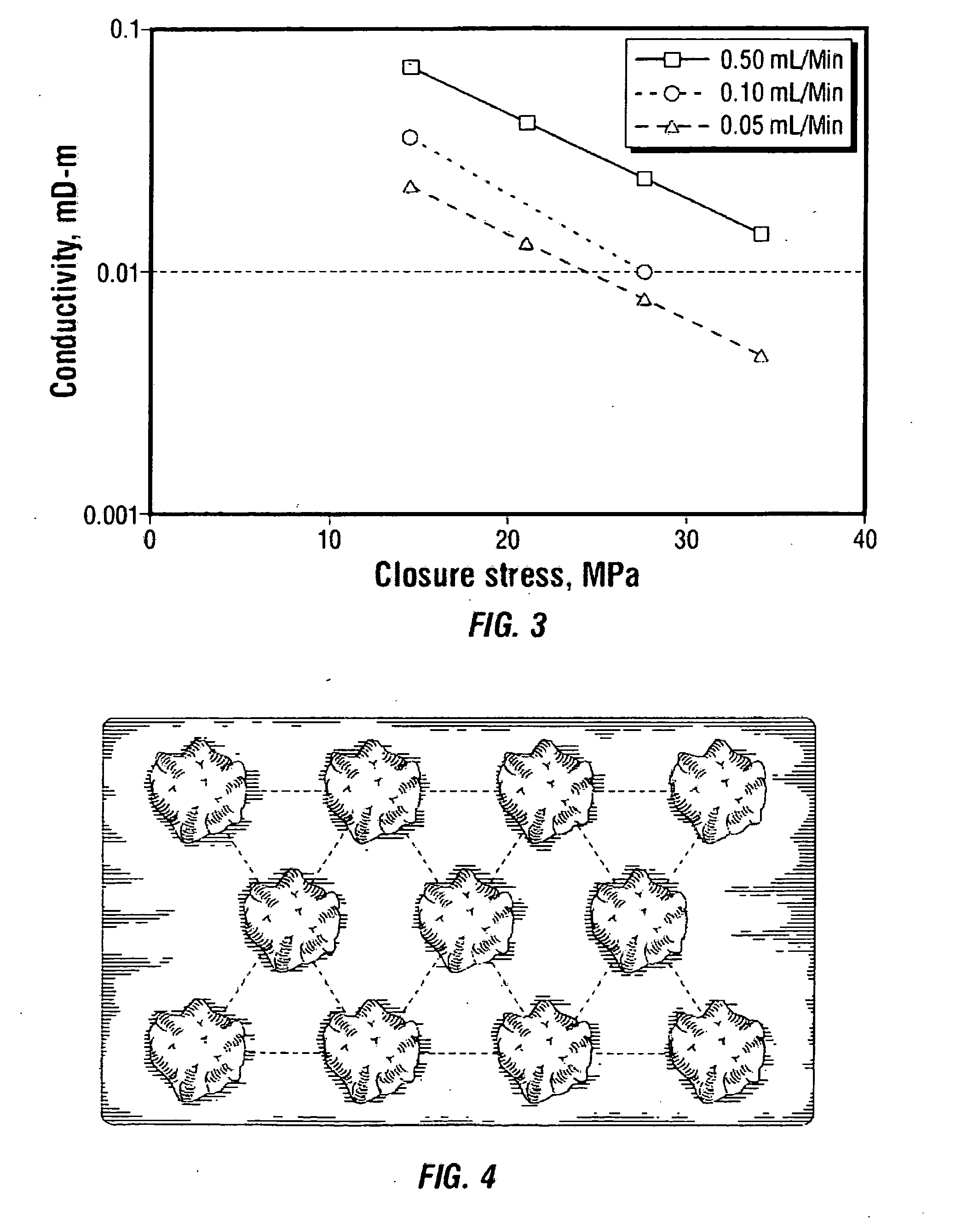
[0121]Conductivity of muscovite mica packs formed from mica with a median particle diameter of 120 microns was measured by means of a Chandler Engineering FRT Model 6100 formation response tester in a split-core set-up. The mica was loaded uniformly at 0.5 kg / m (0.1 lb / ft) between two metal cores, which were compressed with closure stresses of 13.8, 20.7, 27.6, and 34.5 MPa (2000, 3000, 4000 and 5000 psi). Potassium chloride brine (2 wt %) was pumped through the cell with flow rates of 0.05, 0.1 and 0.5 ml / min. The steady state conductivity data for the mica packs are presented in Table 1 and shown graphically in FIG. 3. The formation of channels in the mica packs was visually confirmed upon disassembly of the conductivity cell, and it was seen that the higher flow rates resulted in relatively larger channel formation.

TABLE 1Conductivity of uniform mica packs at 0.5 kg / m.Closure Stress, MPa (psi)Flow Rate,13.8 (2000)20.7 (3000)27.6 (4000)34.5 (5000)ml / minConductivity, mD-m (mD-ft)0....

example 3

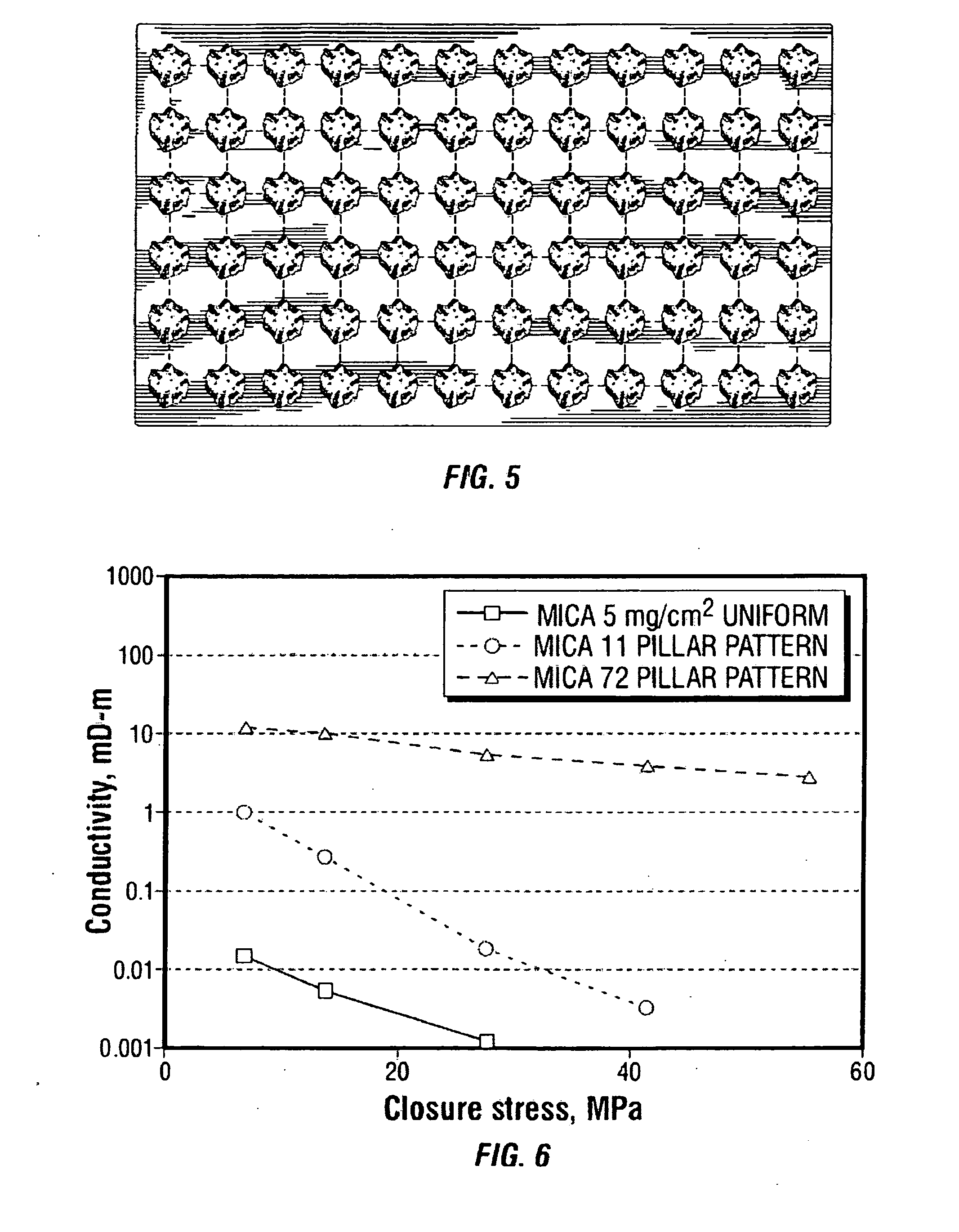
[0122]Conductivity of muscovite mica packs formed from mica with a median particle diameter of 105 microns was measured in a split-core set-up.

[0123]The mica was loaded uniformly or in pillars at 5 kg / m (0.01 lb / ft) between two Mancos shale cores, which were compressed with closure stresses of 3.4, 6.9, 13.8, 27.6, 41.4 and 55.2 MPa (500, 1000, 2000, 4000, 6000 and 8000 psi). The pillars were arranged in a triangular pattern of 11 pillars in longitudinal rows of 4, 3 and 4 pillars as seen in FIG. 4, or in a 6 by 12 square pattern of 72 pillars, as seen in FIG. 5. Potassium chloride brine (2 wt %) was pumped through the cell with flow rates of 0.05-0.200 ml / min. The steady state conductivity data for the mica packs are presented in Table 2 and shown graphically in FIG. 6. The placement of the mica in the pillar arrangement obtained a relatively higher conductivity than the uniform mica placement. The placement of the mica in the 72-pillar configuration had a higher conductivity relat...


PUM


Abstract

Embodiments of hydraulic fracturing methods disclosed herein use fine mesh proppant. In one embodiment the method is used to fracture a low permeability formation. In one embodiment the method uses flocculation to improve conductivity of a fracture. In one embodiment fluid flow through the fine mesh proppant in the fracture creates a network of connected channels to improve the fracture conductivity.

Description

FIELD OF THE INVENTION[0001]The invention relates to stimulation of wells penetrating subterranean formations, and more specifically to fracturing with injection of proppant into the fracture to form one or more paths of reduced resistance to flow for the production of fluids. Embodiments of this invention are concerned with the placing of proppant in a fracture formed in a formation of low porosity such as a tight gas reservoir.BACKGROUND[0002]Hydraulic fracturing is an important method of reservoir stimulation, which allows significant hydrocarbon production increase. The fracturing treatment usually includes a step of pumping a fracturing fluid loaded with suspended solid particles, referred to as proppant, downhole into a subterranean formation at a pressure exceeding formation fracturing pressure. The resulting fracture is filled with the proppant material. When pumping ceases and the fracture is allowed to close, the solid proppant prevents complete closure the proppant pack f...

Claims


Application Information

Patent Timeline
Patent Type & Authority Applications(United States)
IPC IPC(8): E21B43/267
CPCC09K8/685C09K8/74E21B43/267C09K8/805C09K2208/30C09K8/80
Inventor MAKARYCHEV-MIKHAILOV, SERGEY MIKHAILOVICHFREDD, CHRISTOPHER N.HUGHES, TREVORBARMATOV, EVGENY BORISOVICHGEDDES, JILL F.
Owner SCHLUMBERGER TECH CORP
Why Eureka
Try Eureka