Crane control apparatus

a control apparatus and crane technology, applied in the field of crane control apparatus, can solve the problems of insufficient accuracy of normal crane control applications, insufficient purely kinematic model for calculating the position and/or load velocity of the load from the sensor input, etc., and achieve the effect of avoiding large uncertainties involved in obtaining this acceleration

Inactive Publication Date: 2013-06-27
LIEBHERR WERK NENZING
View PDF13 Cites 32 Cited by
  • Summary
  • Abstract
  • Description
  • Claims
  • Application Information

AI Technical Summary

Benefits of technology

[0010]The present invention shows a crane control apparatus for a crane where a load is suspended on a crane cable from a cable suspension point of the crane. The crane control apparatus comprises an observer for estimating at least the position and / or velocity of the load from at least one sensor input of a first sensor by using a physical model of the load suspended on the crane cable. The crane control apparatus of the present invention is characterized in that the physical model of the observer uses the load position and / or the load velocity as a state variable. The inventors of the present invention have realized that this choice of the state vector has a strong impact on the input values necessary for the observer.
[0014]In a preferred embodiment, the present invention provides a crane control apparatus for controlling the position and / or velocity of the load suspended on the rope by using feedback control, where the position and / or the velocity of the load is determined by the observer and used as feedback. The present invention uses an observer design where an inertial coordinate system is used for modelling the load swing. This eliminates the need of measuring the boom tip acceleration and therefore improves the observer performance during acceleration phases.
[0019]However, in a preferred embodiment, the observer of the present invention is independent of the acceleration of the cable suspension point. Thereby, the large uncertainties involved in obtaining this acceleration can be avoided.
[0020]This is possible in the present invention because the acceleration of the cable suspension point only plays a minor role for the state variables used for the observer. It has to be noted that when an exact non-linear model is used, the acceleration of the cable suspension point plays a role at higher orders of the dynamics of the load position and / or the load velocity. However, in the present invention, the acceleration of the cable suspension point can be set to 0 without significantly deteriorating the model output. Therefore, when a non-linear model is used, the acceleration of the cable suspension point is preferably set to 0.
[0022]The model used in the observer may at least comprise a model of the pendulum dynamics of the load suspended on the cable. However, the model may also take into account other effects that might have an influence on the measurement values of the first sensor. For example, the observer may comprise a disturbance model for sensor offset. Thereby, effects of an offset of the sensor can be eliminated. Further, the observer may comprise a disturbance model for string oscillation of the cable. Thereby influences of such oscillations may be reduced. Further, the observer of the present invention may take into account sensor noise and / or process noise.

Problems solved by technology

However, this position and / or load velocity of the load can usually not be measured directly, but has to be calculated from measurements that do not directly describe the load position and / or load velocity but related quantities.
However, because of measurement noise and other uncertainties, a purely kinematic model for calculating the position and / or velocity of the load from the sensor input of the sensor is often insufficient for providing the exactness required by usual crane control applications.

Method used


Image

  • Crane control apparatus
  • Crane control apparatus
  • Crane control apparatus

Examples


Embodiment Construction

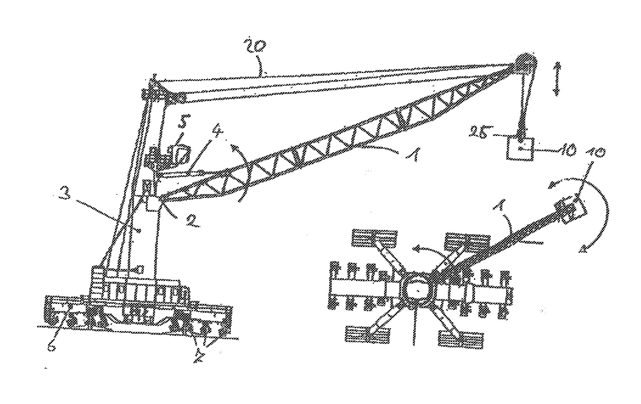
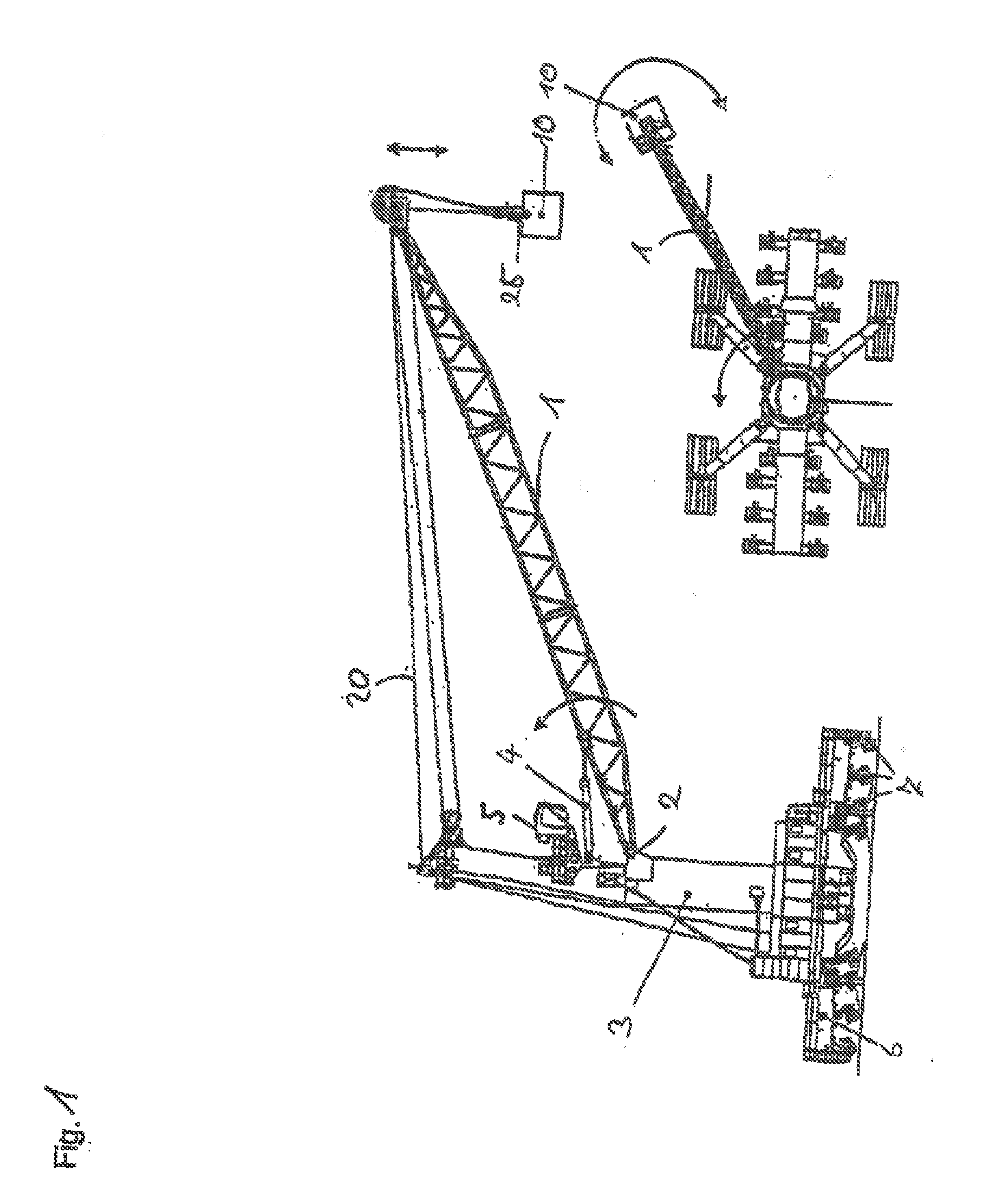
[0053]FIG. 1 shows an embodiment of a crane according to the present invention, in particular of a harbour mobile crane as it is used for moving loads in a harbour. The crane may have a load capacity of up to 140 t and a cable or rope length of up to 80 m.

[0054]The embodiment of the crane of the present invention comprises a boom 1, which can be luffed up and down around a horizontal luffing axis 2, with which the boom is linked to a tower 3. The tower 3 may be turned around a vertical slewing axis by which the boom 1 is slewed, as well. The tower 3 is further mounted on an undercarriage 6, which is moveable by driving units 7. For slewing the tower 3, a slewing drive that is not shown in the figure is used. For luffing the boom 1, the hydraulic cylinder 4 is used.

[0055]The cable or rope 20 to which the load 10 is attached is guided around a pulley arranged at the boom tip, the boom tip therefore forming the cable suspension point for purposes of the present invention. The length of...


PUM


Abstract

The present invention relates to a crane control apparatus for a crane where a load is suspended on a crane cable from a cable suspension point of the crane, comprising an observer for estimating at least the position and / or velocity of the load from at least one sensor input of a first sensor by using a physical model of the load suspended on the crane cable, whereby the physical model of the observer uses the load position and / or the load velocity as a state variable.

Description

BACKGROUND OF THE INVENTION[0001]The present invention is directed to a crane control apparatus for a crane where a load is suspended on a crane cable from a cable suspension point of the crane.[0002]For the control of the crane, exact information on the position and / or the velocity of the load is of great importance. However, this position and / or load velocity of the load can usually not be measured directly, but has to be calculated from measurements that do not directly describe the load position and / or load velocity but related quantities.[0003]For example, in many crane control apparatuses, the cable angle and / or the cable angle velocity is measured by a sensor, from which the load position and / or velocity is calculated. For example, a gyroscope located on a cable follower can be used for measuring cable angle velocity.[0004]However, because of measurement noise and other uncertainties, a purely kinematic model for calculating the position and / or velocity of the load from the s...

Claims


Application Information

Patent Timeline
Patent Type & Authority Applications(United States)
IPC IPC(8): B66C13/06B66C13/00
CPCB66C13/06B66C13/00F02D2041/1417F02D41/021B66C13/085B66C13/063
Inventor SCHNEIDER, KLAUSSAWODNY, OLIVERSAGERT, CONRADSCHAPER, ULF
Owner LIEBHERR WERK NENZING
Why Eureka
Try Eureka