
Energy-based Oriented Switching Mode Power Supply

a power supply and energy-based technology, applied in the direction of electric variable regulation, process and machine control, instruments, etc., can solve the problems of limiting the application range, affecting the efficiency of power supply, and mainly affecting the power supply efficiency so as to reduce the switching loss of the bi-directional converter and achieve the effect of sufficient energy

Inactive Publication Date: 2013-06-27
NATIONAL CHUNG CHENG UNIV
View PDF7 Cites 10 Cited by
  • Summary
  • Abstract
  • Description
  • Claims
  • Application Information

AI Technical Summary

Benefits of technology

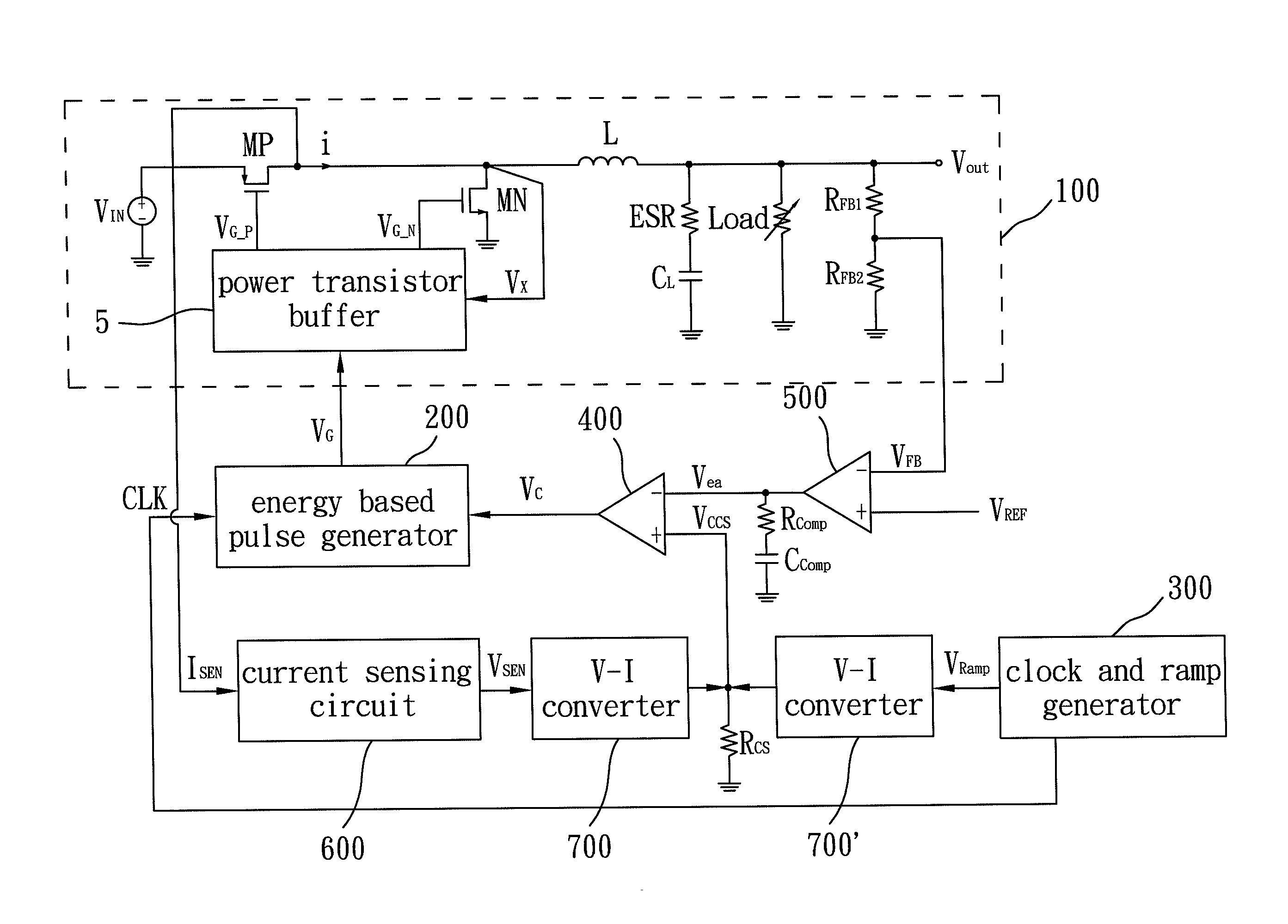
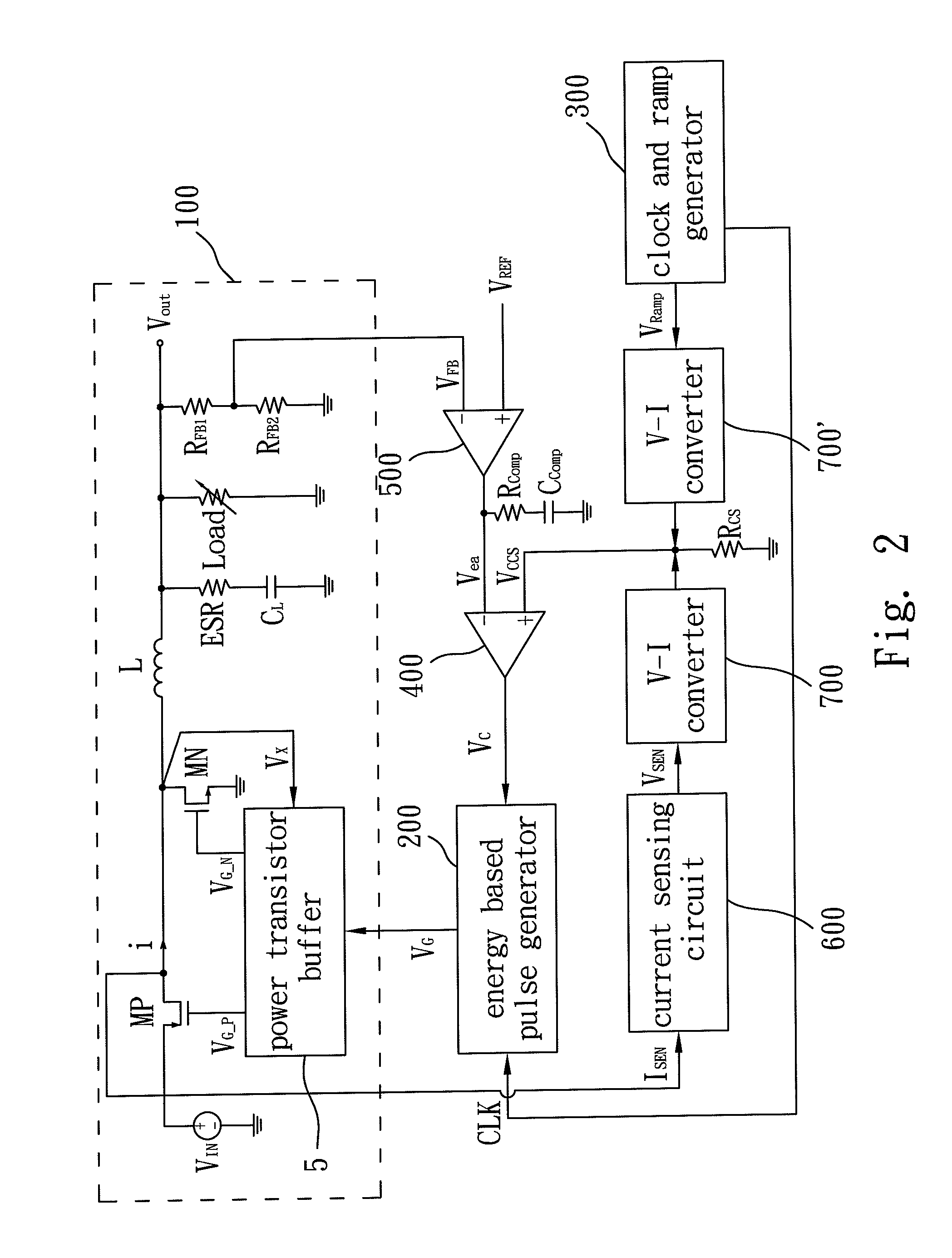
The present invention is an energy-based oriented switching mode power supply that uses only one single control circuit to quickly switch a power MOS of the converter on or off based on the energy demand of the load circuit. It achieves a best operating mode. The power supply also combines PWM and PFM techniques to achieve a fast transient response and reduce voltage ripple while improving power efficiency over a wide load range. The energy based pulsed generator can adjust the gate voltage signal based on the load output, providing sufficient energy to the load output and reducing switching losses. It also increases the switching frequency to provide sufficient energy to the load output when the load output is changing from light to heavy load.

Problems solved by technology

To be more specific, the Low-Dropout Linear Regulator has lower power transfer efficiency and can only be applied to buck converters, thereby limiting its application range.
For example, in bulk converter designs, power losses come mainly from conduction losses with a heavy load while switching losses dominate with a light load.
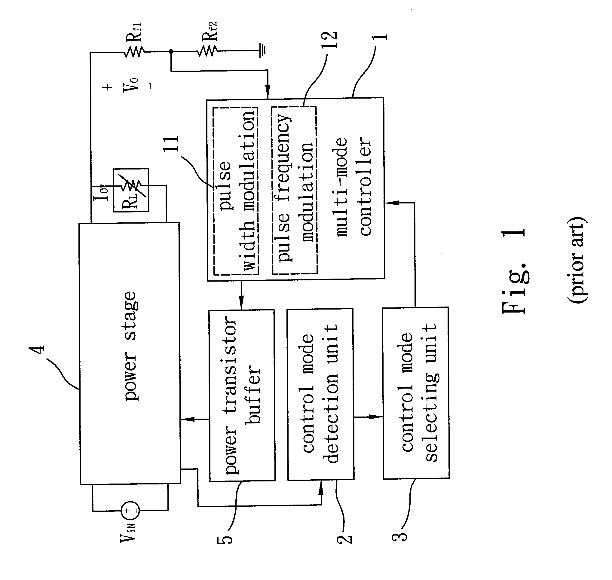
As a result, the converter is complicated and incurs significant voltage variation during changes in the operation mode.

Method used


Image

  • Energy-based Oriented Switching Mode Power Supply
  • Energy-based Oriented Switching Mode Power Supply
  • Energy-based Oriented Switching Mode Power Supply

Examples


Embodiment Construction

[0027]The purpose, construction, features, functions and advantages of the present invention can be appreciated and understood more thoroughly through the following detailed description with reference to the attached drawings. And, in the following, various embodiments are described in explaining the technical characteristics of the present invention.

[0028]The proposed invention provides a novel energy-based oriented switching mode power supply, whose main control circuit, an Energy Based Pulsed Generator (EBPG) can be applied to all kinds of switching mode power supplies.

[0029]The proposed energy-based oriented switching mode power supply achieves a hybrid of PWM and PFM, that adjusts a duty cycle (or duty period) and a switching frequency of the converter to switch its power on or off, depending on the energy demand of the load circuit. In this manner, the energy-based oriented switching mode power supply having an energy-based pulse generator is advantageous of a fast transient r...


PUM


Abstract

An energy-based oriented switching mode power supply includes a bi-directional converter having an energy input and a load output, and an energy based pulsed generator connected between the energy input and the load output for outputting a gate voltage signal controlling how much energy is supplied from the energy input. The energy based pulsed generator receives a clock signal and outputs the gate voltage signal according to the load output of the bi-directional converter when the clock signal is at a high level. Accordingly, the switching mode power supply achieves a hybrid of PWM and PFM, depending on the energy demand of the load output, for a fast transient response and a small voltage ripple whilst improving power efficiency over a wide load range.

Description

BACKGROUND OF THE INVENTION[0001]1. Field of the Invention[0002]The present invention relates to a switching mode power supply, and in particular to a switching mode power supply having an Energy Based Pulsed Generator.[0003]2. The Prior Arts[0004]In recent technology development, DC to DC converters have become one of the widely used power supplies, and can be divided into three types of Buck converters, Boost converters, and Buck-Boost converters due to their different voltage-modulating characteristics. Therefore, three different circuit implementations, including Low-Dropout Linear Regulator, Switching Mode Power Supply, and Switching Capacitor Power Supply, which is respectively carried out by the buck converter, boost converter, and buck-Boost converter, are commonly required in many types of portable devices for extending the battery life.[0005]To be more specific, the Low-Dropout Linear Regulator has lower power transfer efficiency and can only be applied to buck converters,...

Claims


Application Information

Patent Timeline
IPC IPC(8): G05F3/02
CPCH02M3/158Y02B70/16H02M2001/0035H02M1/0035Y02B70/10
Inventor HUANG, CHUNG-HSUNCHEN, CHAO-CHUN
Owner NATIONAL CHUNG CHENG UNIV
Learn More