System and Method for Automated Testing of an Electric Cable Harness

a technology of automatic testing and electric cables, applied in the direction of pulse reflection methods, line-transmission details, instruments, etc., can solve the problems of increased manufacturing costs, electrical failure, unnecessary delay, etc., and achieve the effect of efficient system

Inactive Publication Date: 2013-06-27
PSIBER DATA SYST
View PDF8 Cites 65 Cited by
  • Summary
  • Abstract
  • Description
  • Claims
  • Application Information

AI Technical Summary

Benefits of technology

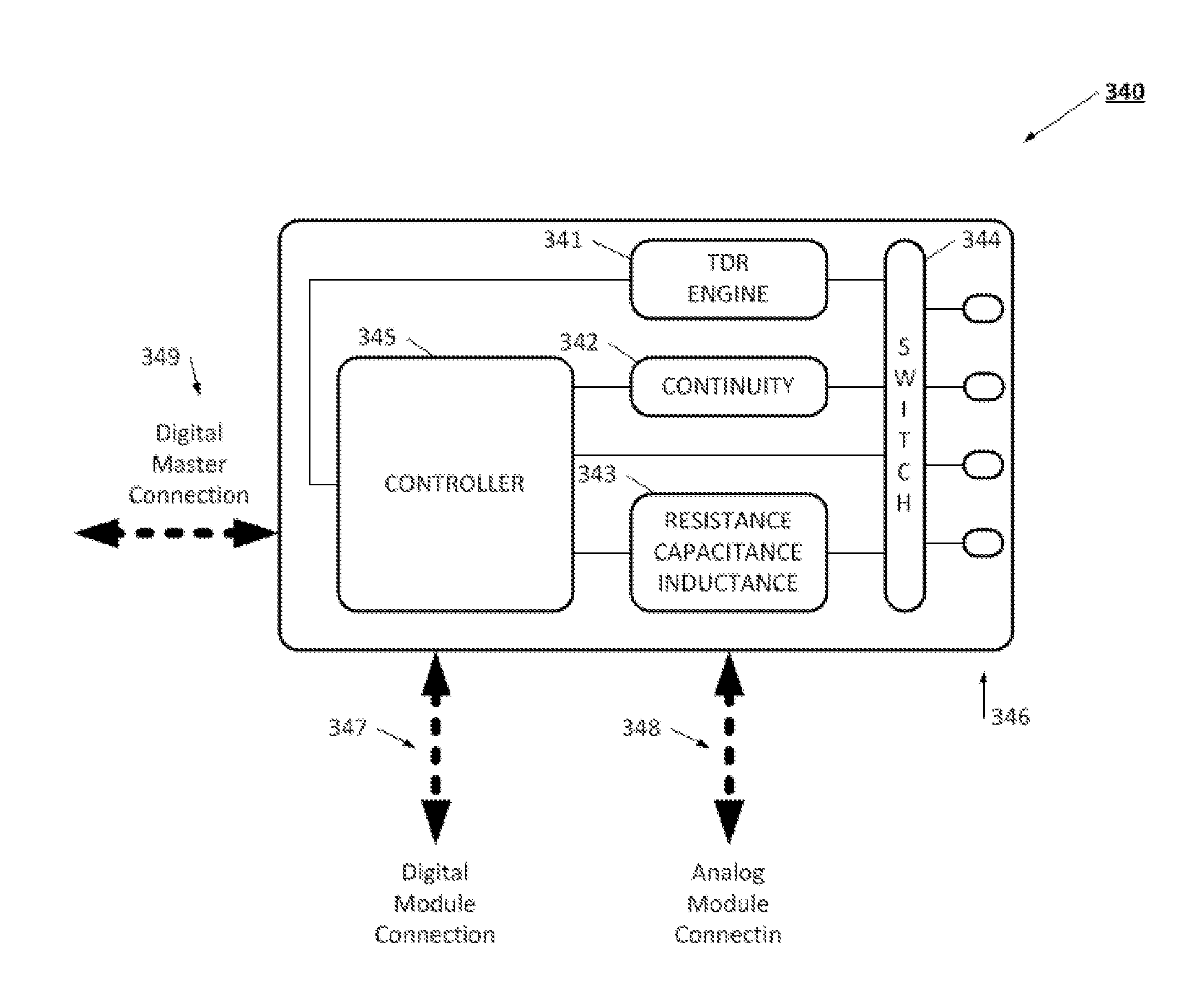
[0046]In one design, the tester is constructed to have a set of TDR engine cards that can be received into a frame. In this way, a large number, for example 24, TDR channels can be used at one time. Each of the TRD channels connects to the switch, which connects each of the TDR channels to a different wire pair in the cable harness. In this way, substantially all the wire pairs in the cable harness can be evaluated using TDR measurement in a highly efficient manner. The switch may use relays or solid state switches for selecting the wire pair for testing. Solid state switches can improve efficiency and increase routing flexibility for selecting a wire pair.
[0049]Advantageously, the tester enables an efficient system for performing a quality assurance test on a cable harness. By using the pre-defined test limits based on standard waveforms, and detecting deviations therefrom, the tester is able to identify latent defects that otherwise remain undetected.

Problems solved by technology

The substantial limitations in current cable testing procedures and devices leads to two different and very undesirable consequences.
First, cable harnesses are shipped to assembly facilities with an existing undetected defect, and the defect is not discovered until sometime later in the assembly process.
This causes unnecessary delay and disruption to fast-moving modern manufacturing processes, leading to down-time and increased manufacturing costs.
For example, an assembly plant may assemble an entire vehicle, and then discover in final test that some electrical failure exists because of a faulty cable harness.
Second, and even worse, the cable assembly might pass all the factory tests, but then one or more electrical lines fail soon after delivery to a customer.
Still worse, such latent wiring defects are often intermittent, making it harder, more expensive, and more frustrating to identify the problem.
This leads to potential safety issues, customer dissatisfaction, and a potentially expensive and time-consuming warranty repair.
It has been estimated that almost 25% of warranty claims are related to these later discovered wiring defects, and these claims are individually relatively expensive.
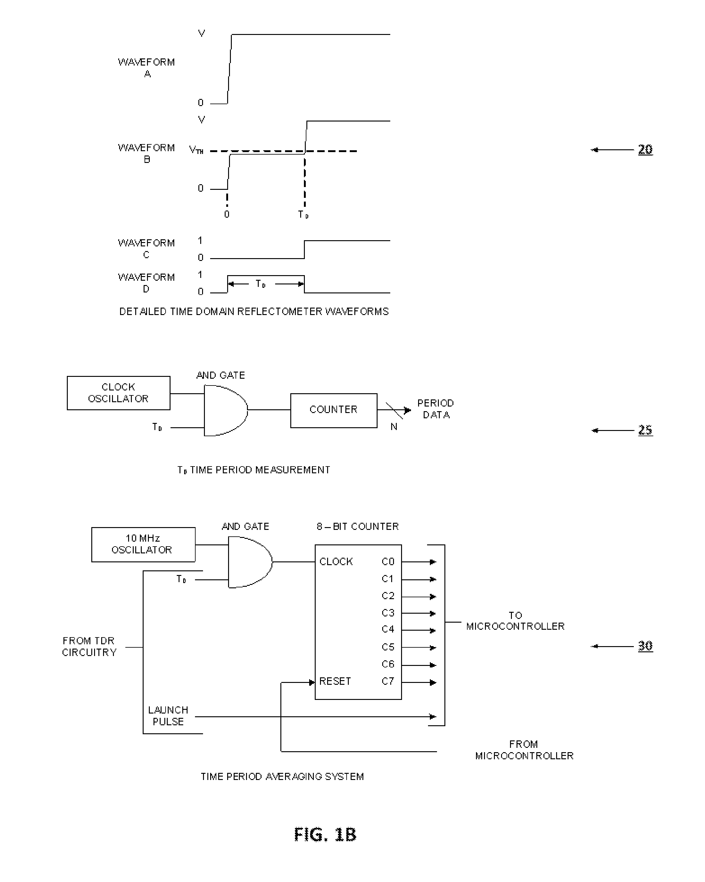
A 19 bit counter operating at 20 GHz is impractical if not impossible.
Also 16.8 MHz is not a readily available frequency.
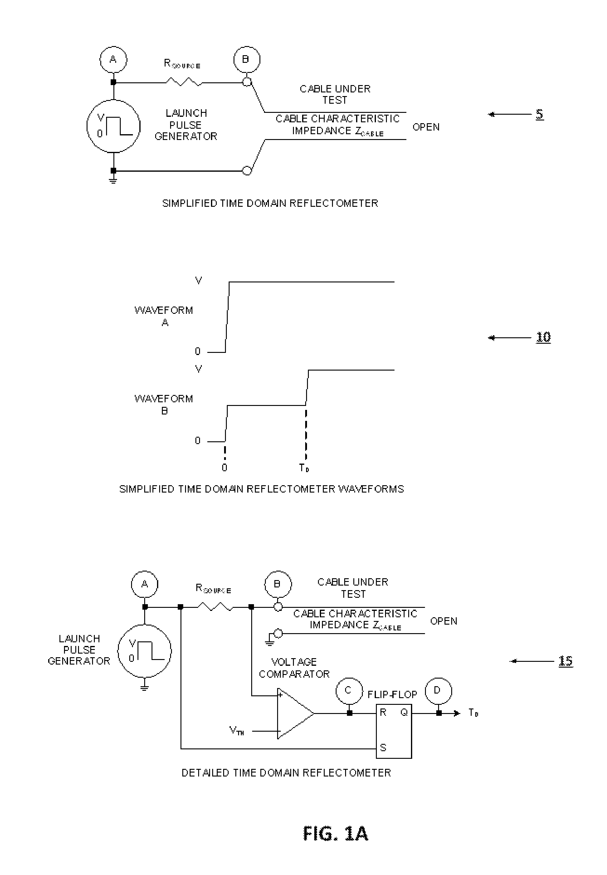
The dead zone is the result of the use of non-ideal components in the TDR circuitry.
The time delay of the voltage comparator actually helps reduce the dead zone as this time delay increases the time delay between the assertions of the flip-flop set and reset inputs.
Although these methods are simple they are not very elegant and are susceptible to process and temperature variations and are inefficient in terms of area and or volume.
Depending on the implementation technique used in the design, the time period averaging counter can interfere with the TDR launch clock, producing non-linearities and dead spots in the measurement due to injection locking of the voltage comparator.
When large numbers of bits transition at the same time very large power supply transient currents flow which can corrupt the TDR voltage comparator and related circuitry.

Method used


Image

  • System and Method for Automated Testing of an Electric Cable Harness
  • System and Method for Automated Testing of an Electric Cable Harness
  • System and Method for Automated Testing of an Electric Cable Harness

Examples


Embodiment Construction

[0063]Referring now to FIG. 2, a typical cable harness is illustrated. In particular, harness 100 is a relatively simple harness for a passenger car, and may be particularly constructed for use in providing electrical and communication interconnection for a single passenger car door. It will be understood that the disclosure of the present invention can be used on many different types and complexities of electrical harnesses, and is applicable on products other than motor vehicles. For example, airplanes, spacecraft, ships and boats, heavy-duty equipment, machinery, appliances, instrumentation, consumer electronics, computers, displays and other electrically powered devices all use cable harnesses to efficiently route electrical, power, and communication lines. It will also be understood that the harness may comprise many different kinds of lines, such as power, digital, analog, and ground, and that these wires come in many sizes and materials, or may be formed as individual wires, ...


PUM


Abstract

Briefly, a method and system for testing a cable harness is disclosed. Generally, a cable harness is used to route many electric wires for power, communication, and control. The tester includes a switch system that enables one or more TDR engines to sequentially apply a TDR stimulus to substantially all the wire pairs in the cable harness, and to collect the resulting TDR waveforms. The waveforms are analyzed to determine if the cable harness meets quality standards. In some cases the tester may also perform a continuity, resistance, capacitance, or inductance test on the cable harness. The tester may also measure and use temperature in analyzing the cable harness, or may apply temperature cycling, different or varying atmospheric pressures, vibration, shaking, or shock to the cable harness.

Description

RELATED APPLICATIONS[0001]This application claims priority to U.S. patent application No. 61 / 498,054, filed Jun. 17, 2011, and entitled “Cable Assembly Test System,” which is incorporated herein as if set forth in its entirety.FIELD OF THE INVENTION[0002]The invention relates generally to a system and method for performing electronic testing on a set of electric cables. In one embodiment, the invention provides a testing platform for automated quality testing of a complex electric wire harness assembly.BACKGROUND[0003]Modern products have become increasing sophisticated, requiring complex electrical interconnections to provide power, control, and monitoring functionality to various assemblies and components within the product. For example, motor vehicles, such as passenger cars, often have scores of embedded computers to provide monitoring and control for operation, safety, convenience, information, entertainment, and emission control purposes. These processors need to be connected ...

Claims


Application Information

Patent Timeline
Patent Type & Authority Applications(United States)
IPC IPC(8): G01R31/02
CPCG01R31/11G01R31/021G01R31/58
Inventor JOHNSON, DARRELL J.MCCOSH, JOHN C.MARMOLEJO, SARA
Owner PSIBER DATA SYST
Why Eureka
Try Eureka