Enhanced edge focus tool

a tool and edge focus technology, applied in the field of machine vision inspection systems, can solve the problems of unsuitable edge focus tools for reliably focusing, unpredictability of gradient influence, and inability to accurately focus

Inactive Publication Date: 2013-06-27
MITUTOYO CORP
View PDF16 Cites 65 Cited by
  • Summary
  • Abstract
  • Description
  • Claims
  • Application Information

AI Technical Summary

Benefits of technology

[0005]This summary is provided to introduce a selection of concepts in a simplified form that are further described below in the Detailed Description. This summary is not intended to identify key features of the claimed subject matter, nor is it intended to be used as an aid in determining the scope of the claimed subject matter.

Problems solved by technology

This type of autofocus, which is used in various known autofocus tools, is not suitable for focusing on an edge located adjacent to a beveled surface feature because different portions of the bevel are in focus and out of focus in different images of the image stack, and as a result, the focus curve has a broader peak, or a poorly defined peak such that the accuracy and repeatability of autofocus under these circumstances is problematic.
However, that edge focus tool is unsuitable for reliably focusing on an edge adjacent to a beveled surface feature.
For various workpiece configurations, this influences the gradient unpredictably in various images.
Furthermore, the workpiece may not include any material beyond the edge adjacent to the beveled surface feature, i.e., that edge is the end of the workpiece, or a workpiece surface on that side may fall outside of the range of a practical image stack such that the gradient may have unpredictable characteristics which will cause the edge focus tool to fail.
Thus, edge features located near a beveled surface feature have proven difficult for known implementations of autofocus; thus, a new approach is required.
Focus operations near an edge of such a feature are often unreliable and may be prone to failure, as outlined above.
However, when a surface is tilted or curved relative to the image plane, e.g., along a chamfered edge of a workpiece, a poor quality, broad focus curve may be provided which is not suitable for reliable focus operations.
In addition, due to effects of lighting reflected along an edge adjacent to a bevel, conventional autofocus measurements (e.g., contrast or gradient measurements) near such an edge may behave unpredictably.

Method used


Image

  • Enhanced edge focus tool
  • Enhanced edge focus tool
  • Enhanced edge focus tool

Examples


Embodiment Construction

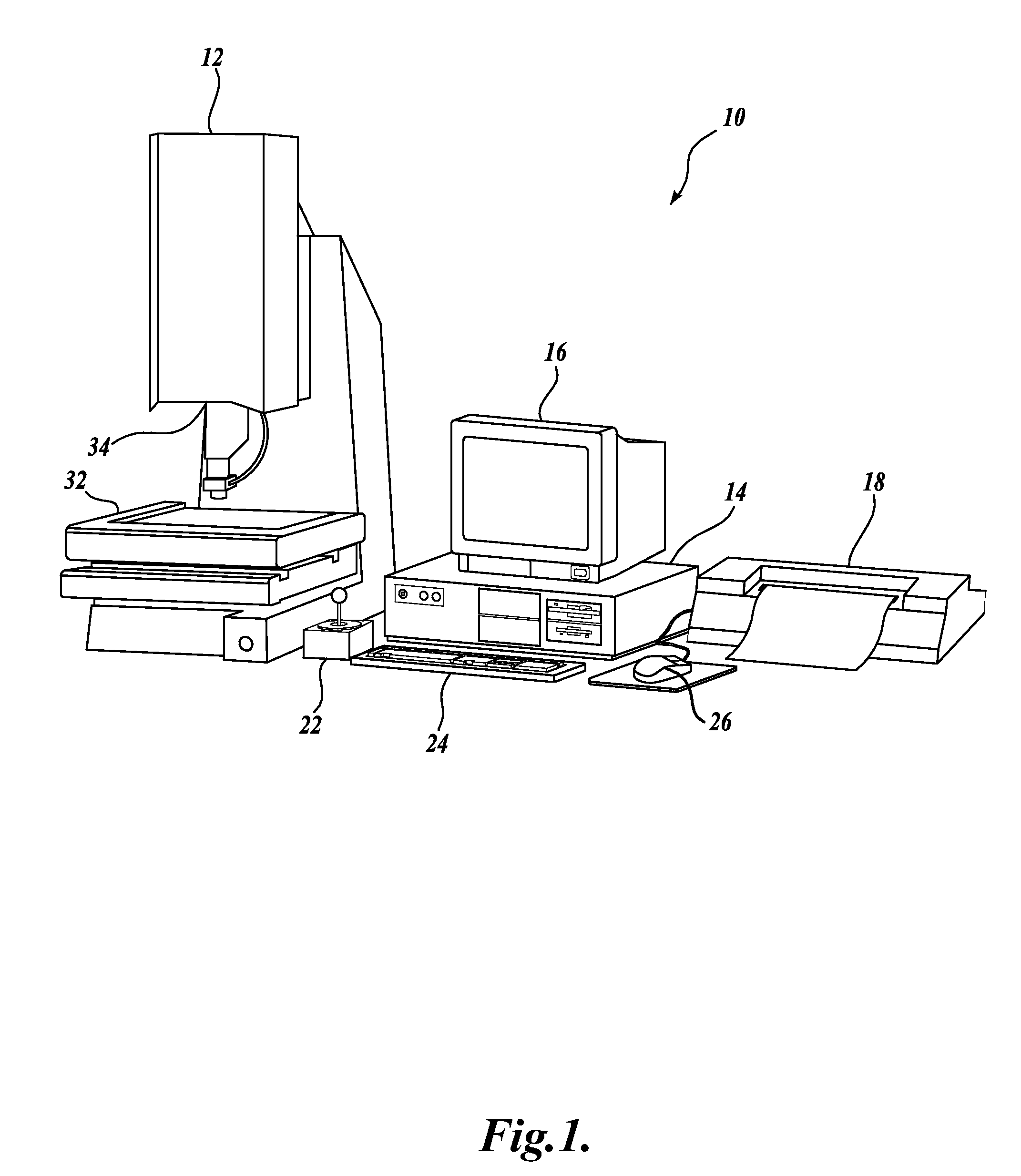
[0022]FIG. 1 is a block diagram of one exemplary machine vision inspection system 10 usable in accordance with methods described herein. The machine vision inspection system 10 includes a vision measuring machine 12 that is operably connected to exchange data and control signals with a controlling computer system 14. The controlling computer system 14 is further operably connected to exchange data and control signals with a monitor or display 16, a printer 18, a joystick 22, a keyboard 24, and a mouse 26. The monitor or display 16 may display a user interface suitable for controlling and / or programming the operations of the machine vision inspection system 10.

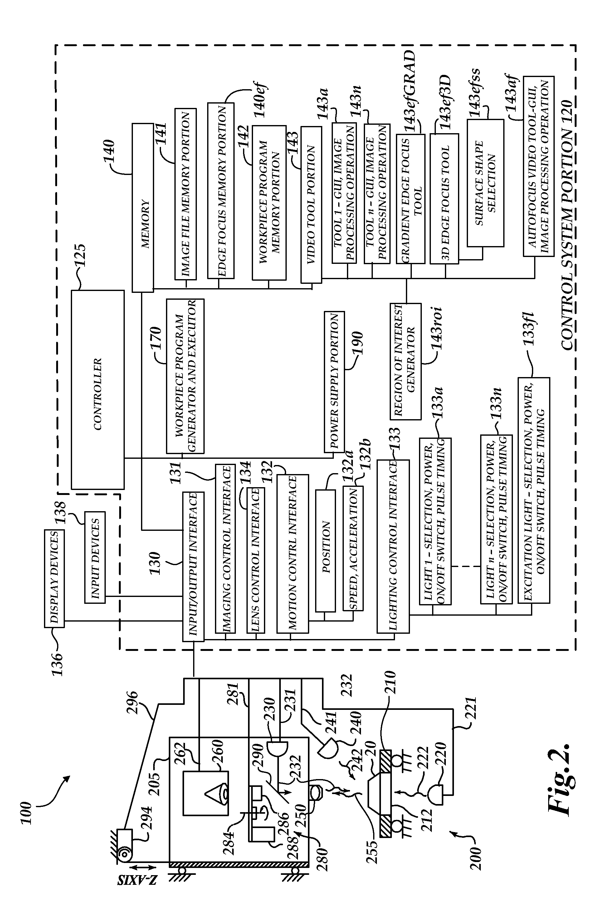
[0023]The vision measuring machine 12 includes a moveable workpiece stage 32 and an optical imaging system 34 which may include a zoom lens or interchangeable lenses. The zoom lens or interchangeable lenses generally provide various magnifications for the images provided by the optical imaging system 34. The machine vision insp...


PUM


Abstract

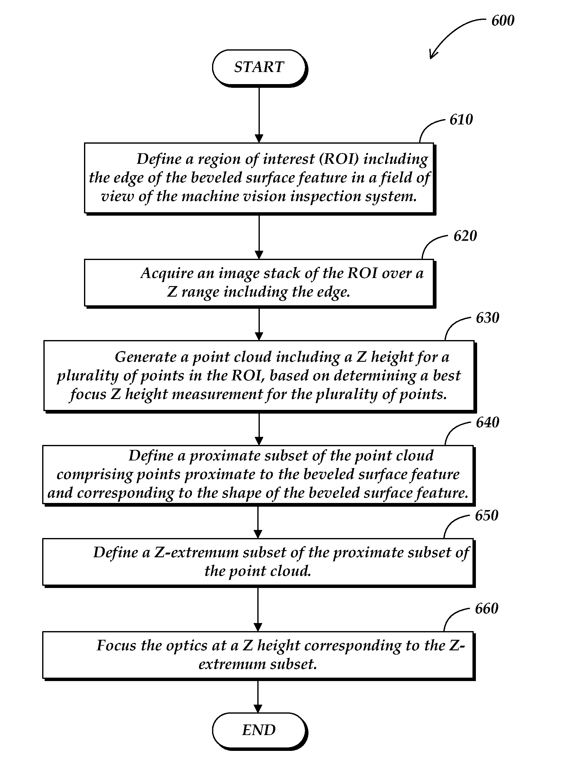
A method for operating an edge focus tool to focus the optics of a machine vision inspection system proximate to an edge adjacent to a beveled surface feature is provided. The method comprises defining a region of interest (ROI) including the edge in a field of view of the machine vision inspection system; acquiring an image stack of the ROI over a Z range including the edge; generating a point cloud including a Z height for a plurality of points in the ROI, based on determining a best focus Z height measurement for the plurality of points; defining a proximate subset of the point cloud comprising points proximate to the beveled surface feature and corresponding to the shape of the beveled surface feature; defining a Z-extremum subset of the proximate subset of the point cloud; and focusing the optics at a Z height corresponding to the Z-extremum subset.

Description

FIELD OF THE INVENTION[0001]The invention relates generally to machine vision inspection systems, and more particularly to methods of focusing a machine vision inspection system at an edge adjacent to a beveled surface.BACKGROUND OF THE INVENTION[0002]Precision machine vision inspection systems (or “vision systems” for short) can be utilized to obtain precise dimensional measurements of inspected objects and to inspect various other object characteristics. Such systems may include a computer, a camera and optical system, and a precision stage that is movable in multiple directions to allow workpiece inspection. One exemplary prior art system, that can be characterized as a general-purpose “off-line” precision vision system, is the commercially-available QUICK VISION® series of PC-based vision systems and QVPAK® software available from Mitutoyo America Corporation (MAC), located in Aurora, Ill. The features and operation of the QUICK VISION® series of vision systems and the QVPAK® so...

Claims


Application Information

Patent Timeline
Patent Type & Authority Applications(United States)
IPC IPC(8): G06K9/00H04N7/18
CPCG01B11/0608G01B11/028
Inventor DING, YUHUACAMPBELL, SHANNON ROYDELANEY, MARK LAWRENCEBRYLL, ROBERT KAMIL
Owner MITUTOYO CORP
Why Eureka
Try Eureka