Rolling bearing

a technology of rolling bearings and rolling bearings, which is applied in the direction of mechanical equipment, rotary machine parts, engine components, etc., can solve the problems of shortening the life of rolling bearings and quickly wearing down of the spherical bearing, so as to reduce the friction coefficient, prevent the vibration of the sealing member, and reduce the wear

Active Publication Date: 2013-06-27
MINEBEAMITSUMI INC
View PDF4 Cites 3 Cited by
  • Summary
  • Abstract
  • Description
  • Claims
  • Application Information

AI Technical Summary

Benefits of technology

[0018]With this structure it is possible to reduce wear so as to prevent vibrations of the sealing member even being difficult to finish the contact surface of the seal contact groove by grinding, because the friction coefficient can be reduced as well as the surface roughness can be decreased by covering the contact surface of the seal contact groove with a solid lubricating coating,.
[0019]As discussed hereinabove, by reducing the central line average roughness (surface roughness) of the seal contact surface of the outer ring or inner ring which contacts the sealing member, and by reducing contact forces (force of the sealing member pressing against the seal contact groove) between the sealing member and the seal contact groove, wear of the sealing member can be reduced, vibration of the sealing member can be decreased, and the occurrence of seal screeching noises can be effectively prevented. In consequence, the life of the rolling bearing is extended, and quietness of the rolling bearing is improved.

Problems solved by technology

Since the rolling bearings in a blower rotate at high speed, the rolling bearings with the surface roughness of the seal contact groove greater than the one of conventional rolling bearings, and with the lip sliding in contact with the roughened surface of the seal contact groove from radial direction, may have the lip wearing down quickly which shortens the life of the rolling bearings.

Method used


Image

  • Rolling bearing
  • Rolling bearing
  • Rolling bearing

Examples


Embodiment Construction

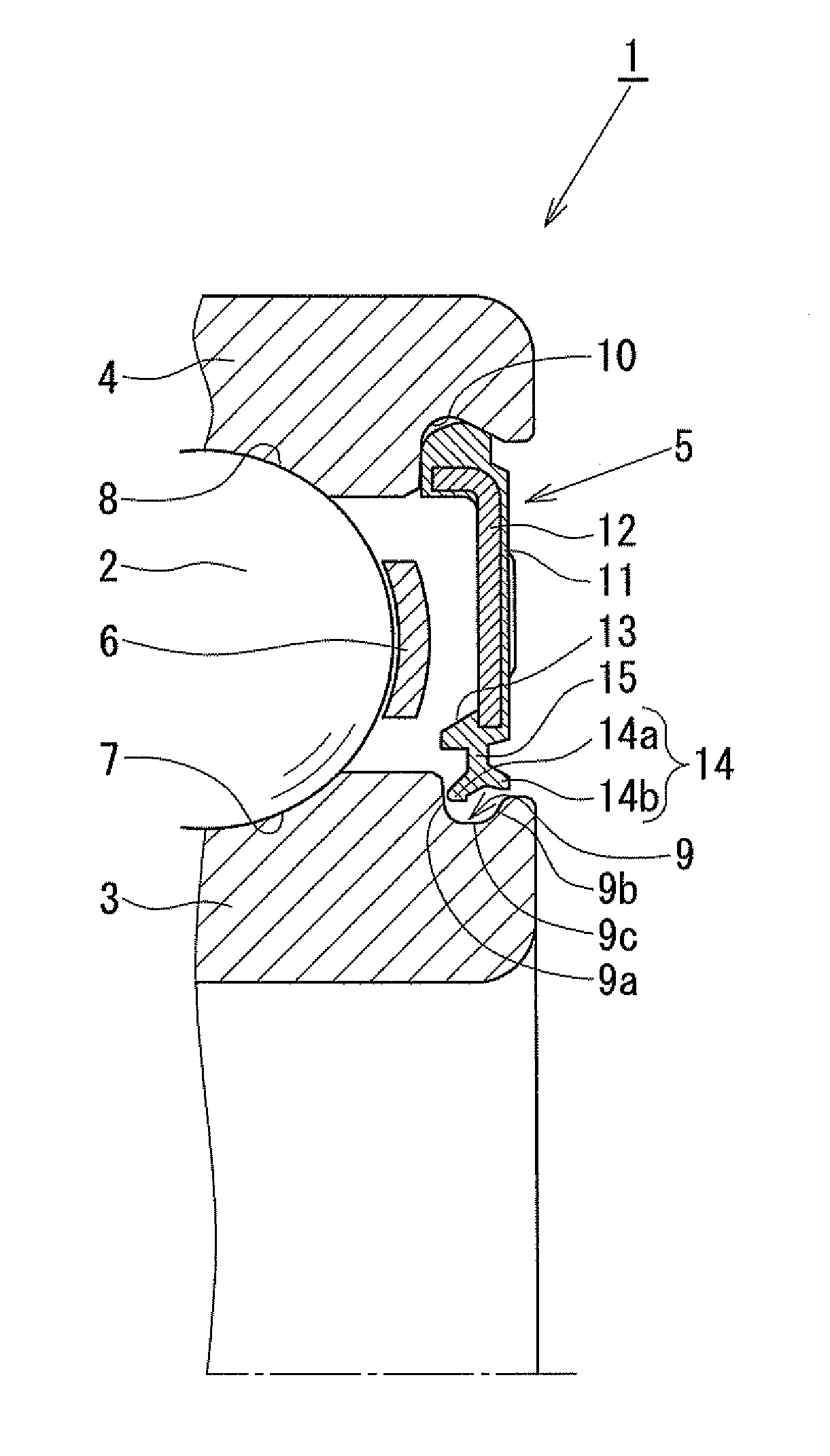
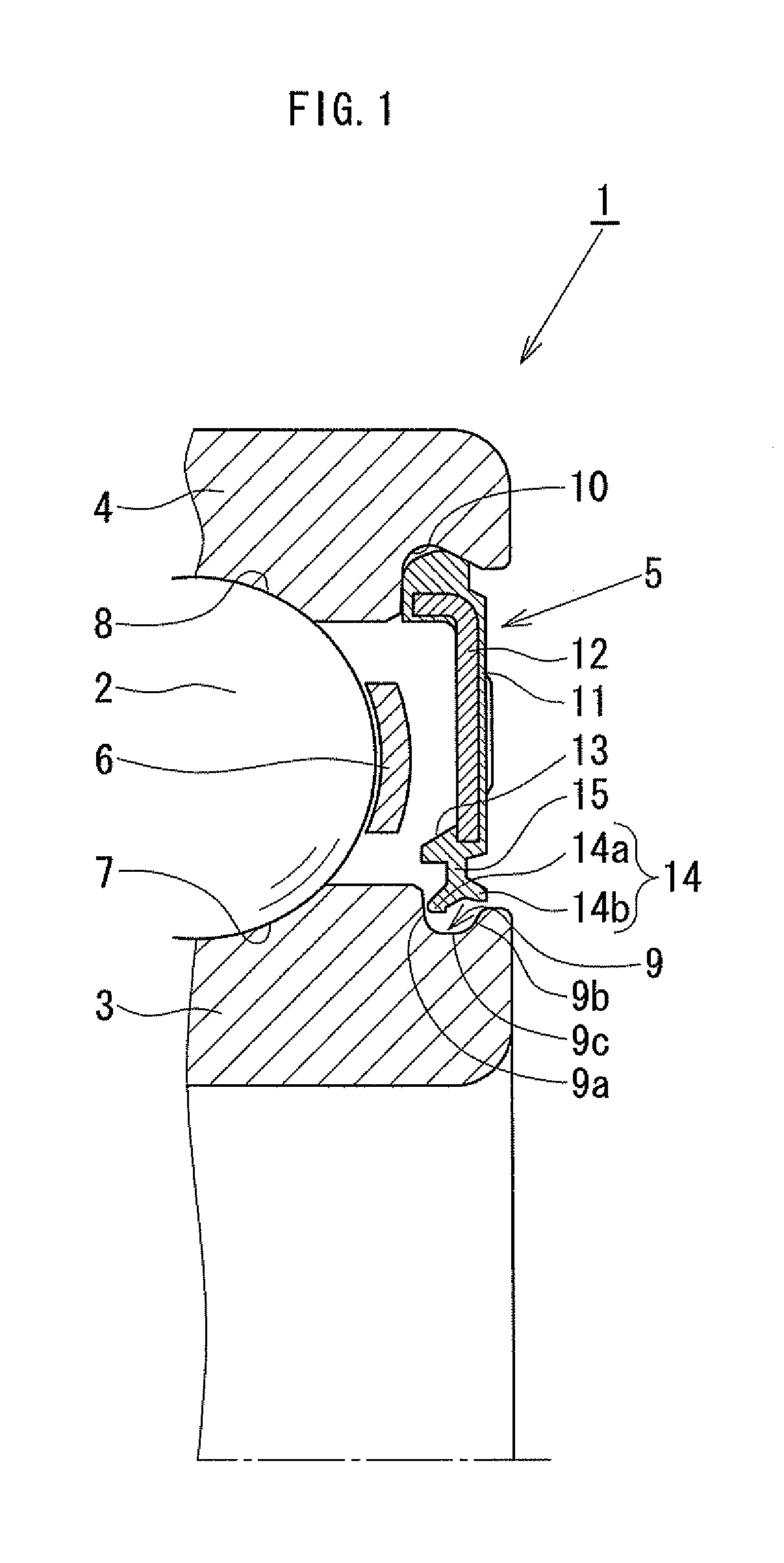
[0029]The structure of a rolling bearing according to one embodiment of the present invention will be explained in detail below based on FIGS. 1 and 2.

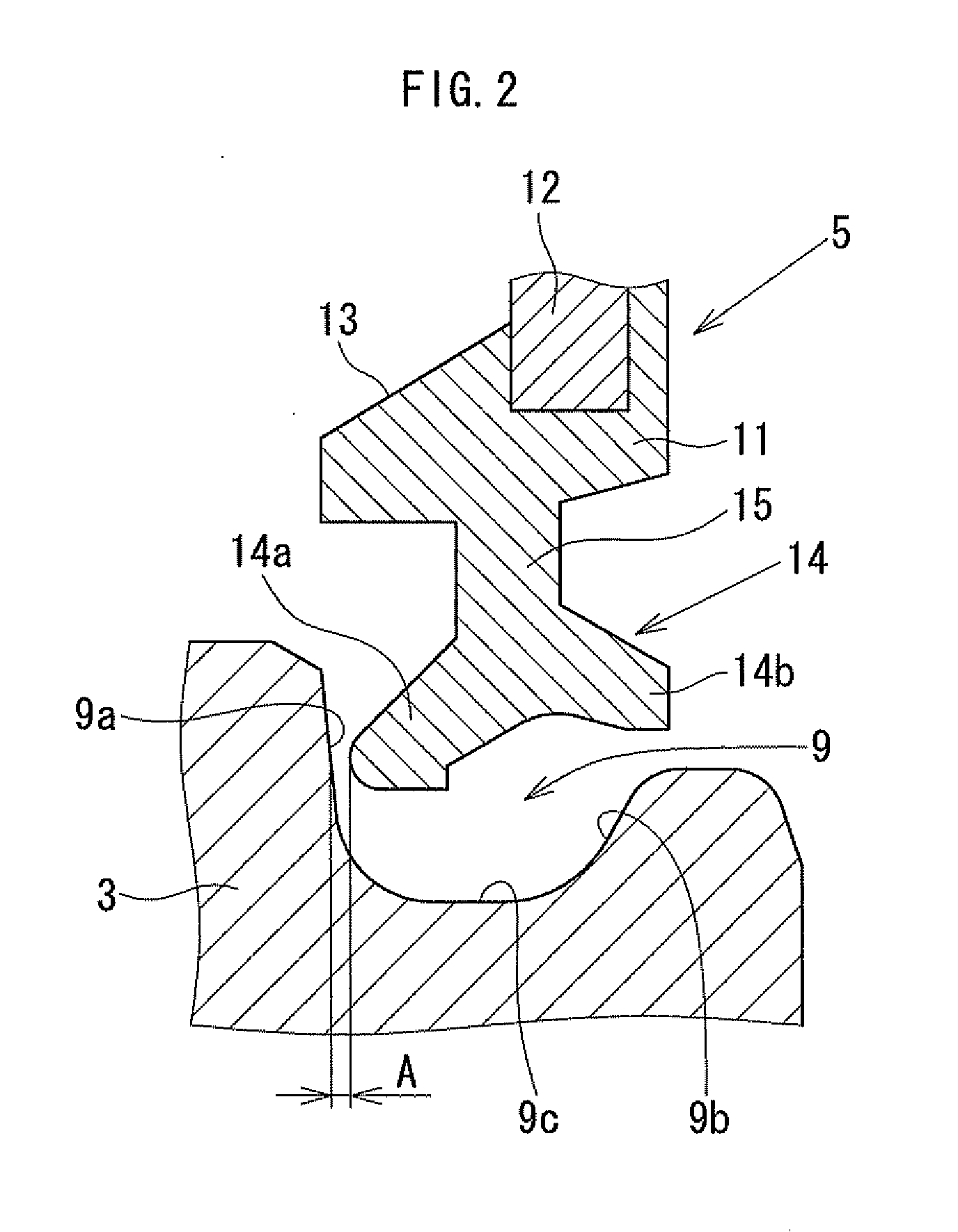
[0030]FIG. 1 is a cross-section view of one end of a rolling bearing according to one embodiment of the present invention, and FIG. 2 is a partially enlarged view of a lip part and a seal contact groove of the rolling bearing shown in FIG. 1. As shown in FIG. 1, a rolling bearing 1 of the present embodiment supports a shaft member of a motor, and the rolling bearing 1 includes an inner ring 3, an outer ring 4, a ball (steel ball) 2 which is a rolling element interposed between the inner ring 3 and the outer ring 4, a sealing member 5, and a retainer 6. Hereinbelow, the constituent members of the rolling bearing 1 is explained. Only one end side of the rolling bearing 1 is illustrated, but the other end side may be structured as the same.

[0031]On the inner ring 3, an inner ring raceway 7 is formed at the center of the outer peripheral ...


PUM

PropertyMeasurementUnit
surface roughnessaaaaaaaaaa
inner diameteraaaaaaaaaa
surface roughnessaaaaaaaaaa

Abstract

A rolling bearing has an inner ring; an outer ring; a seal fixing groove provided at either the inner ring or the outer ring; a seal contact groove provided at either the inner ring or the outer ring on a side where the seal fixing groove has not been provided; and a sealing member with two ends. One end of the sealing member is fitted into the seal fixing groove, and the other end of the sealing member is configured not to contact the seal contact groove in a non-preloaded state but to contact the seal contact groove in an axial direction in a preloaded state. Further, a central line average roughness Ra of a contact surface of the seal contact groove to which the sealing member contacts is Ra≦0.6 μm.

Description

BACKGROUND OF THE INVENTION[0001]1. Field of the Invention[0002]The present invention relates to a rolling bearing, and more particularly to a rolling bearing which has a contact type sealing member including two ends. When one end thereof is fitted into either an outer ring or an inner ring of the rolling bearing, the other end thereof is configured to contact either the outer ring or the inner ring into which the one end has not been installed.[0003]2. Description of the Related Art[0004]In many cases, the rotating shaft of a motor is rotatably supported by a pair of preloaded rolling bearings. There is a sealed-type rolling bearing, in which a sealing member is fitted in between an inner ring and an outer ring of such a rolling bearing in order to keep grease, lubricating oil, or the like and / or in order to prevent the ingress of foreign particles into a bearing space between the inner ring and the outer ring of the rolling bearing. Further, there is a sealing member of the rolli...

Claims


Application Information

Patent Timeline
Patent Type & Authority Applications(United States)
IPC IPC(8): F16C33/76
CPCF16C33/76F16C2360/46F16C2220/60F16C33/782F16C33/7853F16C33/583F16C33/64F16C2240/54F16C2206/04F16C2223/02F16C19/06F16C2380/26
Inventor YAMAMOTO, TAKUYAKOMIYAMA, HIROSHI
Owner MINEBEAMITSUMI INC
Why Eureka
Try Eureka