Variable Displacement Oil Pump

Inactive Publication Date: 2013-06-27
HITACHI AUTOMOTIVE SYST LTD
View PDF2 Cites 19 Cited by
  • Summary
  • Abstract
  • Description
  • Claims
  • Application Information

AI Technical Summary

Benefits of technology

[0007]According to one aspect of the present invention, there is provided a variable displacement oil pump comprising: a rotor configured to be rotationally driven; a plurality of vanes movable out from and into an outer circumferential portion of the rotor; a cam ring separately forming a plurality of working-oil rooms by receiving the rotor and the plurality of vanes in an inner circumferential space of the cam ring, wherein the cam ring is configured to move to vary an eccentricity between a rotation center of the rotor and a center of an inner circumferential surface of the cam ring and thereby to vary a variation rate of volume of each of the plurality of working-oil rooms which is produced when the rotor rotates; a lateral wall provided on at least one of lateral portions of the cam ring, wherein the lateral wall includes a suction portion open to the working-oil room whose volume is increasing when the rotor is rotating under

Problems solved by technology

However, in the case of the previously-proposed oil pump, it becomes hard for the cam ring to swing with the increase of the discharge pressure since the sp

Method used


Image

  • Variable Displacement Oil Pump
  • Variable Displacement Oil Pump
  • Variable Displacement Oil Pump

Examples


Example

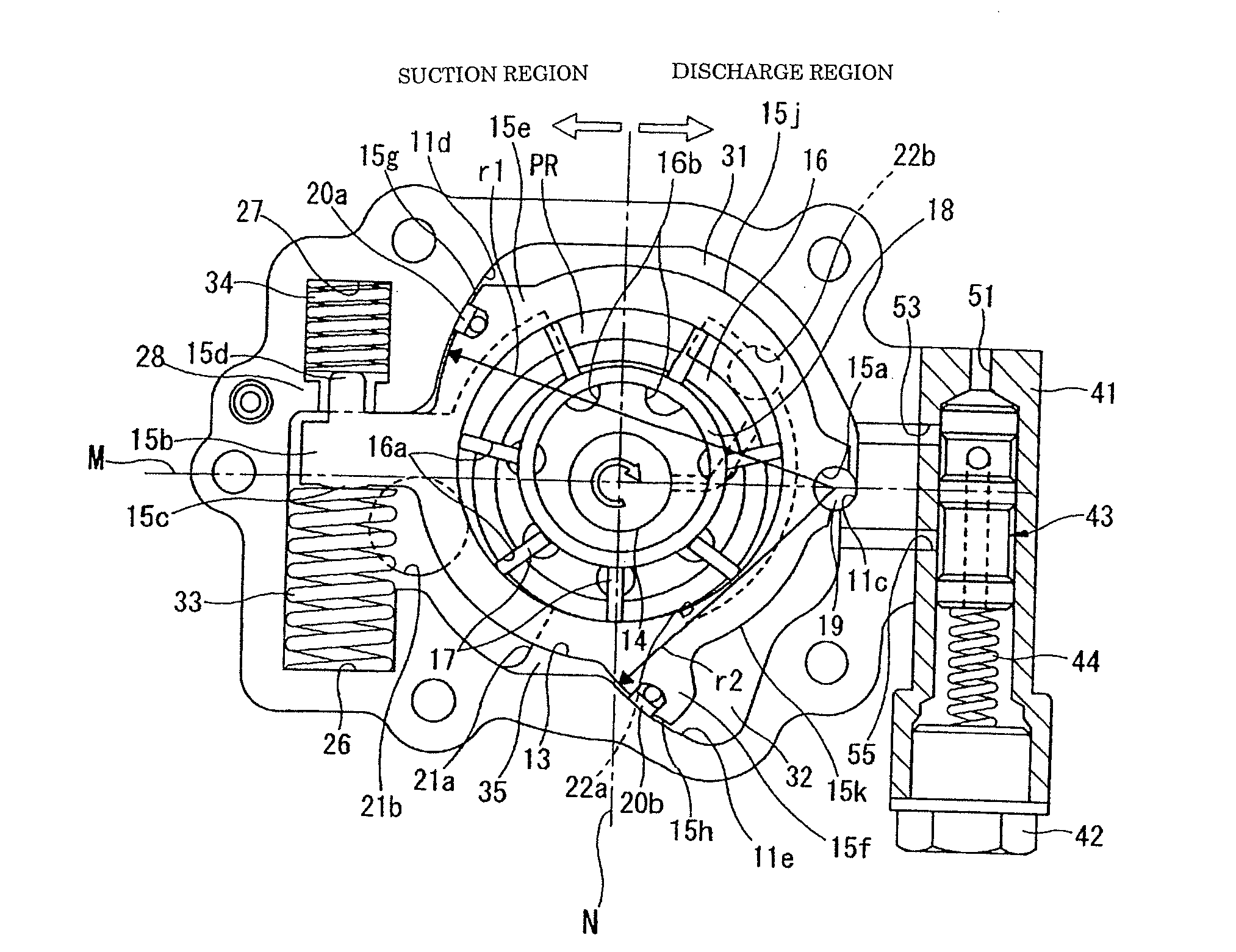
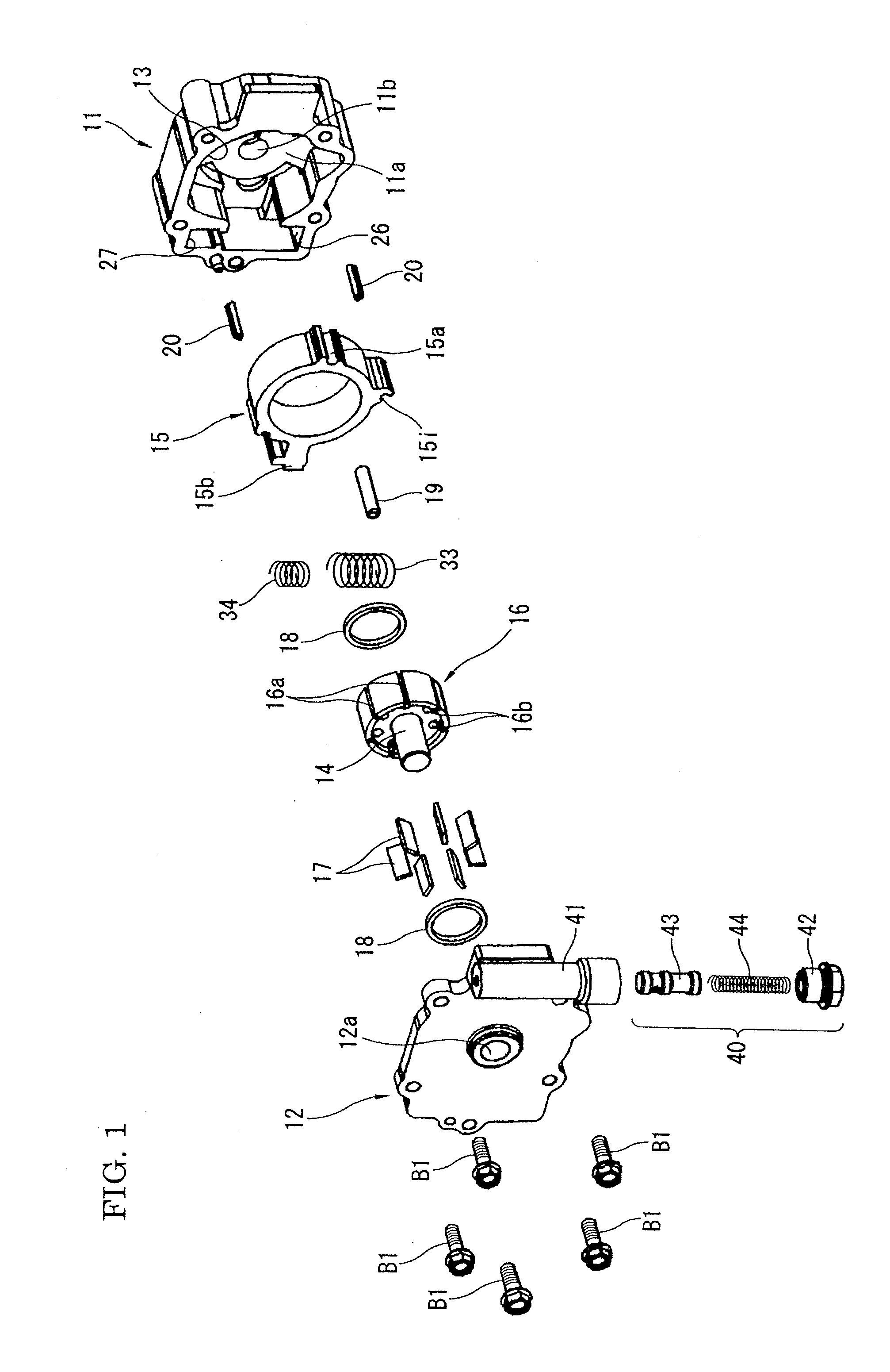
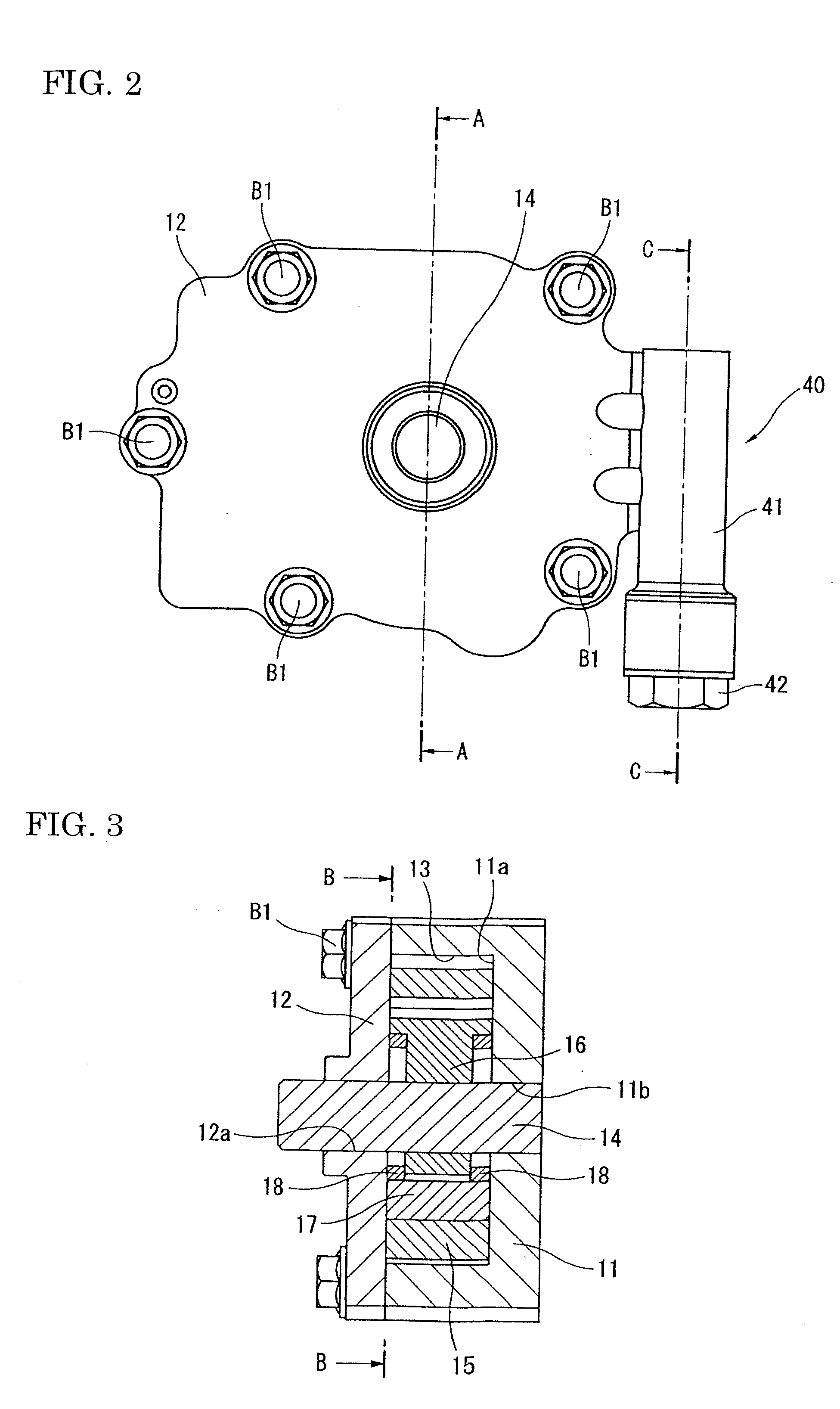
[0022]FIGS. 1 to 9 show an oil pump in a first embodiment according to the present invention. This oil pump 10 is provided to a frontend portion of cylinder block or a balancer device of the internal combustion engine (not shown). As shown in FIGS. 1 to 4, the oil pump 10 includes a pump housing, a drive shaft 14, a cam ring 15, pump constituting members, and a changeover control valve 40. The pump housing includes a pump body 11 and a cover member 12. The pump body 11 is formed substantially in a U shape in cross section taken by a plane parallel to an axial direction of the oil pump. That is, axially one end side of the pump body 11 is open such that a pump accommodation chamber 13 is formed inside the pump body 11. The cover member 12 covers or encloses the axially one end opening of the pump body 11. The drive shaft 14 is rotatably supported by the pump housing, and passes through an approximately central portion of the pump accommodation chamber 13. The drive shaft 14 is driven...

Example

[0066]FIG. 10 shows a variable displacement oil pump in a second embodiment according to the present invention. In this second embodiment, the changeover control valve 40 is a solenoid valve SV which operates based on exciting current derived from a vehicle-mounted ECU (not shown) according to an operating state of the engine. That is, the above-mentioned changeover control is electrically performed by driving and controlling the spool valving element 43 by use of the solenoid valve SV. The solenoid valve SV performs the changeover control of the changeover control valve 40 on the basis of rotational speed, water temperature, oil temperature, oil pressure or the like of the internal combustion engine which are sensed by predetermined sensors or the like. Specifically, the changeover control is carried out based on a map corresponding to the graph shown by the solid line in FIG. 8, with reference to parameters of engine rotational speed and oil pressure which have been directly sense...


PUM


Abstract

An oil pump includes first and second control chambers, a biasing mechanism, and a changeover mechanism. The changeover mechanism connects the first control chamber with a drain portion when a valving element is in a first position, introduces a discharge pressure into the first and second control chambers when the valving element reaches a second position, and drains oil of the second control chamber to the drain portion and introduces the discharge pressure into the first control chamber when the valving element reaches a third position. The changeover mechanism changes from the first position to the second position, when the discharge pressure becomes higher than a pressure level at which the cam ring can move against a set load of the biasing mechanism, and is lower than a pressure level at which a biasing force of the biasing mechanism is increased in a stepwise manner.

Description

BACKGROUND OF THE INVENTION[0001]The present invention relates to a variable displacement oil pump adapted to supply working fluid as a hydraulic pressure source.[0002]U.S. Pat. No. 7,794,217 discloses a previously-proposed variable displacement oil pump which is applied to an internal combustion engine for an automobile.[0003]The variable displacement pump disclosed in this patent is a vane-type variable-displacement oil pump. In this technique, an eccentricity amount of a cam ring is controlled in two stages according to rotational speed of the engine, on the basis of spring force of a spring and biasing force of a discharge pressure introduced into two control oil chambers which are separately formed between a pump housing and the cam ring. The spring is provided to bias the cam ring in a direction (hereinafter referred to as “eccentric direction”) that increases the eccentricity amount of the cam ring relative to a rotation center of a rotor. The discharge pressure introduced in...

Claims


Application Information

Patent Timeline
IPC IPC(8): F04C14/22
CPCF04C14/226F04C2/344
Inventor SAGA, KOJI
Owner HITACHI AUTOMOTIVE SYST LTD
Why Eureka
Try Eureka