Energy-saving optimized control system and method for refrigeration plant room

Active Publication Date: 2013-07-04
WELDTECH TECH SHANGHAI
View PDF2 Cites 42 Cited by
  • Summary
  • Abstract
  • Description
  • Claims
  • Application Information

AI Technical Summary

Benefits of technology

[0007]To overcome the shortage in the prior arts, the present invention provides an energy-saving optimized control system for a chiller plant room and a method thereof, which can great

Problems solved by technology

In the prior arts, chillers may operate with lower chilled water supply temperature and lower chilled water flow rate, which may lead to higher energy consumption of the chillers and lower energy consumption of the chilled water pumps.
Likewise, to the same cooling output, chillers can be operated under a lower condensing pressure, which leads to lower energy consumption of the chillers; however, a higher condenser water flow rate is required for the lower condensing pressure, leading to a higher energy consumption of the condenser water pump.
In the prior arts, some methods may be feasible in a stable laboratory condition, however, in the actual operational process, all the apparatuses in the chiller plant room are in the continuously operating state, and the cooling loads and the weather parameters will vary at any moment, which may cause the actual parameter values collected not having regularity, so the energy consumption model can not be optimized an

Method used


Image

  • Energy-saving optimized control system and method for refrigeration plant room
  • Energy-saving optimized control system and method for refrigeration plant room
  • Energy-saving optimized control system and method for refrigeration plant room

Examples


Example

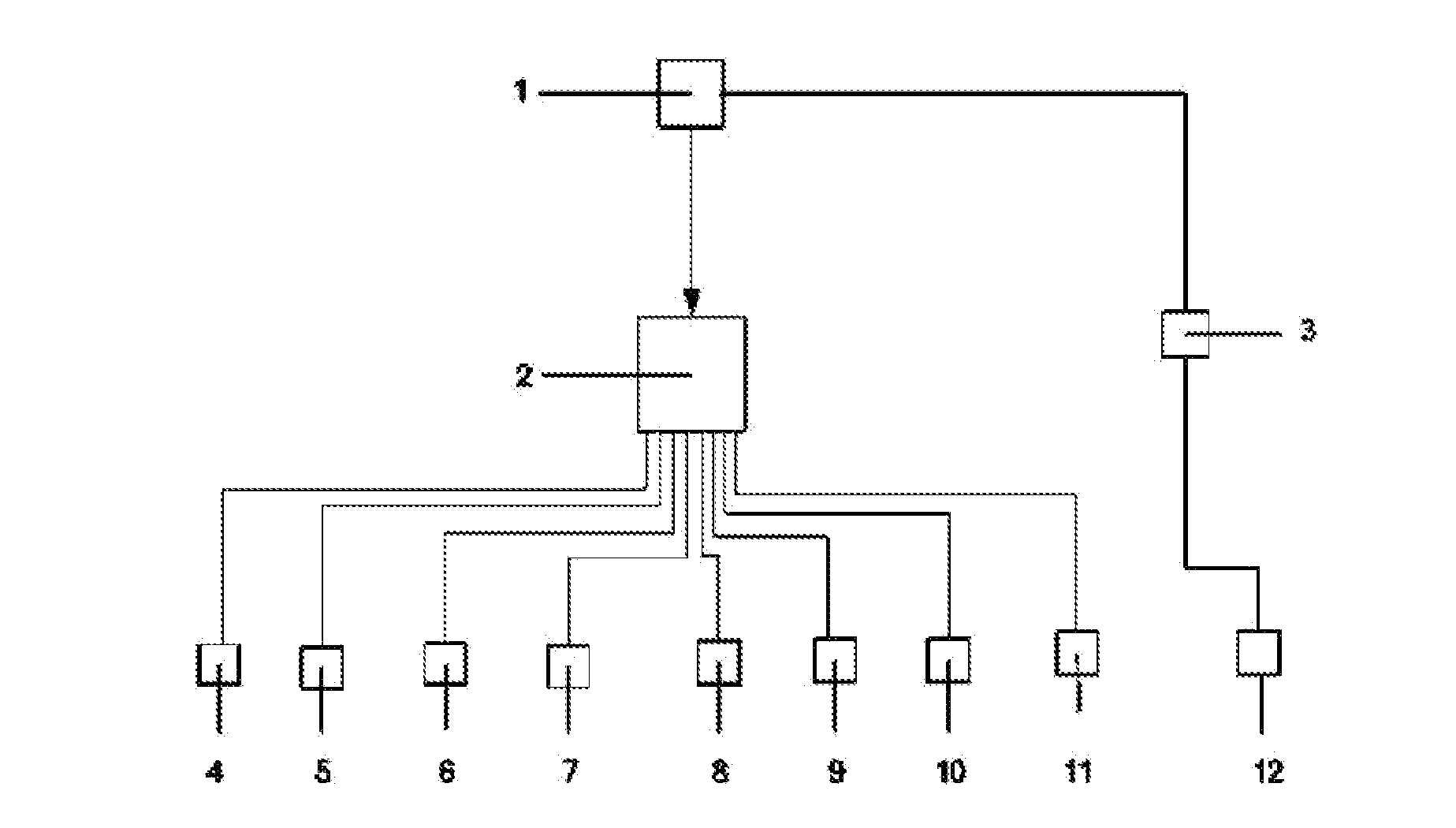
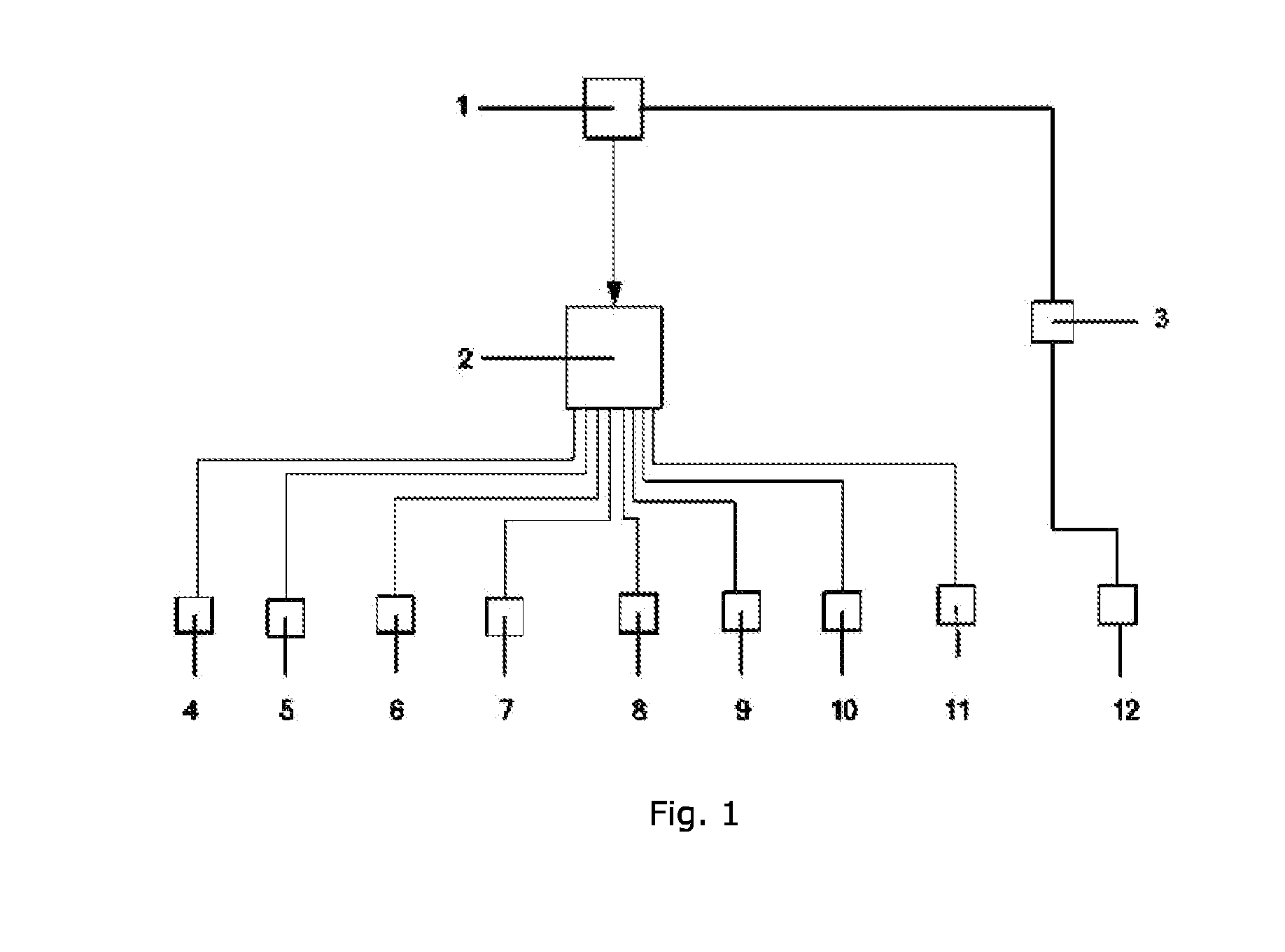
[0065]As shown in the FIG. 1 and FIG. 2, the embodiment of the device according to present invention comprises: a industrial control computer 1, a programmable controller 2, an RS485 communication interface module 3, a flow sensor 4, a temperature sensor 5, an outdoor temperature and humidity sensor 6, a three-phase active power transmitter 7, a differential pressure sensor 8, a water pump variable speed driver 9, a cooling tower fan variable speed driver 10, a motorized valve and on / off actuator 11, and chillers 12.

[0066]According to the present invention, there are provided with a plurality of flow sensors 4, a plurality of temperature sensors 5, one outdoor temperature and humidity sensor 6, a plurality of three-phase active power transmitters 7, a differential pressure sensor 8, a plurality of water pump variable speed drivers 9 and a plurality of cooling tower fan variable speed drivers 10, which are connected with the programmable controller 2 respectively. The programmable co...


PUM


Abstract

An energy-saving optimized control system for a chiller plant room comprises an industry control computer (1), a flow sensor (4), a temperature sensor (5), an outdoor temperature and humidity sensor (6), a three-phase active power transmitter (7), a water pump variable speed driver (9) and a cooling tower fan variable speed driver (10), which are respectively connected with a programmable controller (2), wherein the programmable controller (2) communicates with the industrial control computer (1) through an industrial Ethernet; and an RS485 communication interface module (3) is connected with chillers and communicates with the industrial control computer (1) through a ModBus protocol. An energy-saving optimized control method for a chiller plant room is also provided. By establishing a mathematical model of the relationship between the energy consumption and operation parameters of each equipment in the refrigeration plant room and combining the real-time cooling loads and weather parameters, the operating state of each equipment is adjusted so as to reach the lowest operating energy consumption of the whole chiller plant room under the premise of meeting the cooling loads.

Description

TECHNICAL FIELD[0001]The present invention relates to an energy-saving system and a method thereof, especially to a system for a chiller plant room.TECHNICAL BACKGROUND[0002]For the energy consumption of a whole building, the energy consumption of an air conditioning system takes a great proportion, which is about 40˜50% generally. In addition, for the energy consumption of the air conditioning system, chiller plant room (which comprises chillers, chilled water pumps, condenser water pumps and cooling towers) will take about 60%˜70% Regarding to an office building using an electric cooling, the power consumption for all year of an air conditioning cooling source (chiller plant room), i.e. chillers, chilled and condenser water pumps and cooling towers, will take about 30˜35% of the power consumption of the whole building for all year.[0003]The cooling operational process of an air conditioning system comprises the following. The chillers produce chilled water with predetermined tempe...

Claims


Application Information

Patent Timeline
IPC IPC(8): F25D29/00
CPCG05B15/02G05B2219/2638F25D29/00Y02P80/10F24F11/62F24F11/89F24F11/30G05B19/05
Inventor WONG, HOYUENWU, GANG
Owner WELDTECH TECH SHANGHAI
Why Eureka
Try Eureka