Method and device for handling, in particular for repairing or replacing, busbars on wind power plants

a technology for wind power plants and busbars, applied in the direction of motors, wind energy generation, pile separation, etc., can solve the problems of preventing previously damaged elastomers of the relevant busbars, and inability to repair or replace them, so as to eliminate inherent stresses of all busbars and prevent the introduction of transverse forces

Inactive Publication Date: 2013-07-04
FLYTEG
View PDF3 Cites 9 Cited by
  • Summary
  • Abstract
  • Description
  • Claims
  • Application Information

AI Technical Summary

Benefits of technology

[0006]Proceeding from the presented prior art, the invention is based on the problem of further developing a method for handling, in particular for repairing of replacing, busbars on wind power plants such that a dismantling and mounting of individual busbars on a wind power plant is made possible, without additional stresses or respectively previous damage being introduced into the busbar interconnection composed of the busbars, or respectively that a simple replacement of busbars is made possible.
[0007]The invention is based here on the idea of at least partially equalizing the weight of at least one busbar, arranged directly above or respectively below in particular the busbar which is to be repaired or respectively replaced, by means of a relief arrangement by applying a tensile force to the relevant busbar. Thereby, the inherent stresses between the individual busbars of a busbar subregion are at least reduced, in the best case are completely eliminated, so that the busbars can be removed or respectively dismantled and subsequently mounted again in a stress-free manner.

Problems solved by technology

Owing to the special geometric construction of the busbars, it is not possible, without the risk of damage to individual busbars, to remove an individual busbar from a busbar subregion due to a necessary repair or a necessary replacement.
Owing to the elastic suspension of the busbars and the mentioned stresses between the busbars and between the busbar subregions, on re-mounting of the busbars additional stresses are introduced into the busbar interconnection formed from the individual busbar subregions, which can previously damage the busbar interconnection.
Moreover, during the repair or replacement, the busbars of the busbar above that which is to be repaired or respectively replaced are partially stressed by the weight of busbars arranged above, so that these settle by a certain distance and therefore if applicable the elastomers of the relevant busbars can be previously damaged, which if applicable can not be detected visually.

Method used


Image

  • Method and device for handling, in particular for repairing or replacing, busbars on wind power plants
  • Method and device for handling, in particular for repairing or replacing, busbars on wind power plants
  • Method and device for handling, in particular for repairing or replacing, busbars on wind power plants

Examples


Embodiment Construction

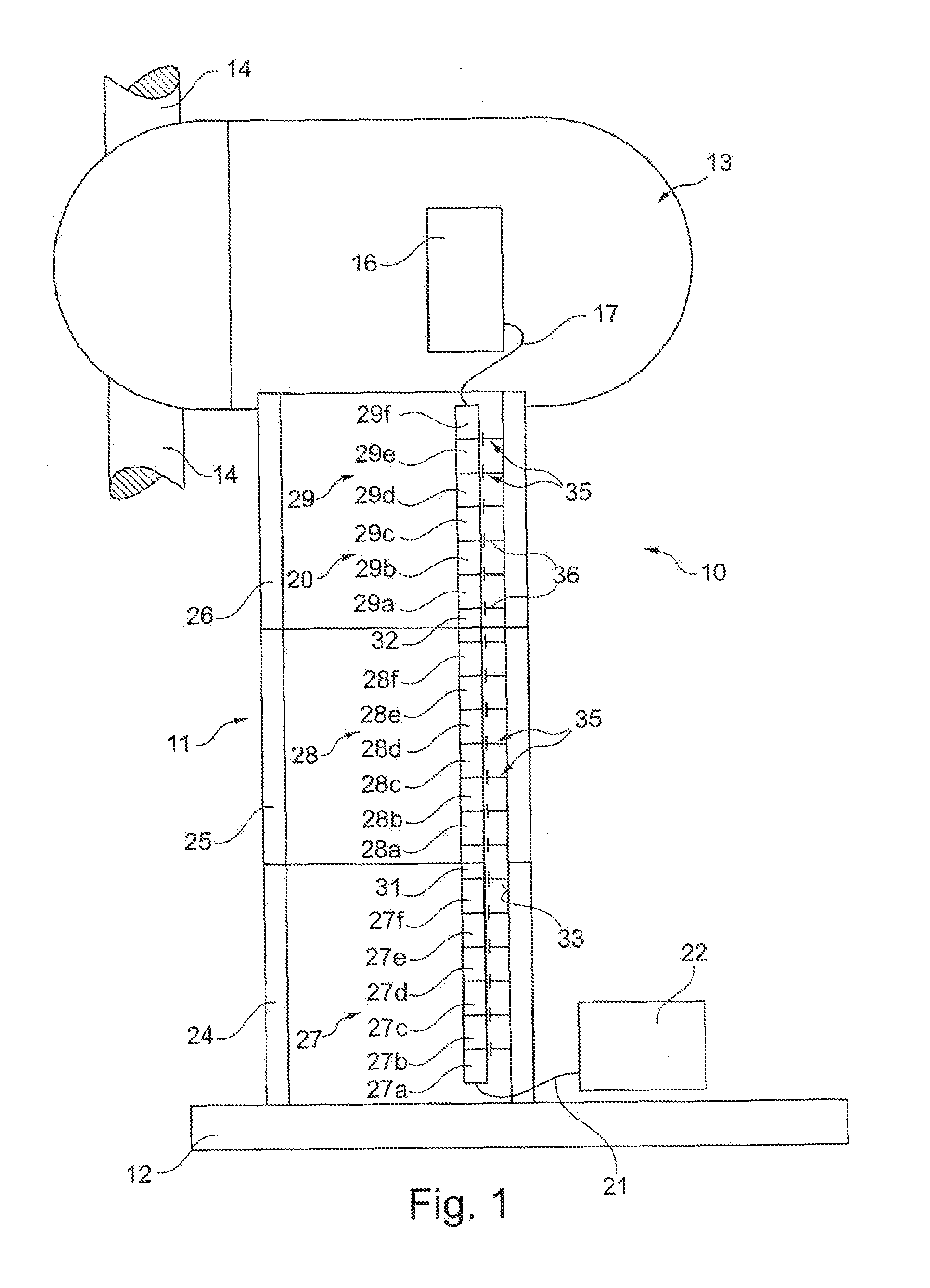
[0025]In FIG. 1 the basic structure of a wind power plant 10 is illustrated in a greatly simplified manner. The wind power plant 10 has a tower 11, which is arranged on a base 12. At the top of the tower 11a nacelle 13 is arranged, in which inter alia the rotor blades 14 are arranged in a rotatably movable manner. A generator 16 is situated within the nacelle 13. The generator 16 is coupled with an upper connecting line 17 or an upper connection with a busbar interconnection 20. The busbar interconnection 20 is arranged here in particular over the entire length or respectively height of the tower 11. In the region of the base 12 of the tower 11, the busbar interconnection 20 is connected by means of a further, lower connecting line 21 or respectively a lower connection with a substation 22.

[0026]The tower 11 consists for example of three respectively sleeve-like tower segments 24 to 26 arranged on top of one another. Such a tower segment 24 to 26 has here a typical length of approxi...


PUM


Abstract

A method for handling busbars on wind power plants in which a power connection between a generator device disposed in an upper region of the wind power plant and a substation located at a base area of the wind power plant consists of a plurality of busbar subregions each comprising a certain number of mutually interconnected busbars.

Description

BACKGROUND OF THE INVENTION[0001]The invention relates to a method for handling, in particular for repairing of replacing, busbars on wind power plants. The invention further relates to a method for handling, in particular for repairing or replacing, bus bars on wind power plants.[0002]In the transmission of the power generated in a generator in the region of the top of a tower of a wind power plant into a substation arranged at the base of the wind power plant, a differentiation is basically made between two methods: In the first method, the power is transmitted via a cable from the generator to the substation. In the second method, the power transmission takes place by means of busbars. Here, for bridging the distance between the base region and the head of the tower of the wind power plant, usually a plurality of busbars are used, connected or respectively screwed to one another, which have, for example, a typical length of approximately 3 m.[0003]The tower of a wind power plant ...

Claims


Application Information

Patent Timeline
Patent Type & Authority Applications(United States)
IPC IPC(8): H02G5/04F03D11/00
CPCF03D1/003F03D11/0058F05B2230/80Y02E10/722H02G5/007H02G5/025H02G5/04H02B3/00F03D80/50F03D80/82Y02E10/72Y02P70/50
Inventor WIECHERS, JOERG
Owner FLYTEG
Why Eureka
Try Eureka