Low emission dry gas seal system for compressors

a compressor and low-emission technology, applied in the field of compressors, can solve the problems of toxic or dangerous to the environment and/or to workers in the plant, the overall system is more complex, and the current dry gas seal system is not fault-free, so as to improve the control of potentially hazardous process gas and reduce complexity and maintenance requirements.

Inactive Publication Date: 2013-07-04
NUOVO PIGNONE SPA
View PDF2 Cites 20 Cited by
  • Summary
  • Abstract
  • Description
  • Claims
  • Application Information

AI Technical Summary

Benefits of technology

[0011]Exemplary embodiments provide sealing mechanisms usable, e.g., for centrifugal compressors. A sealing mechanism includes first, second and third dry gas seals arranged in series. Each seal receives its own sealing gas and has its own venting mechanism. Sealing gas pressures which separate the process gas from the venting system remain low enough that a dedicated compressor for supplying the sealing gases is not needed. Advantages according to exempl

Problems solved by technology

Various types of gases are used in centrifugal compressors, some of which are toxic or dangerous to the environment and/or to workers in the plants.
Centrifugal compressors equipped with these types of dry gas sealing systems thus also require additional compressors whose function is solely to provide the

Method used


Image

  • Low emission dry gas seal system for compressors
  • Low emission dry gas seal system for compressors
  • Low emission dry gas seal system for compressors

Examples


Embodiment Construction

[0021]The following detailed description of the exemplary embodiments refers to the accompanying drawings. The same reference numbers in different drawings identify the same or similar elements. Also, the following detailed description does not limit the invention. Instead, the scope of the invention is defined by the appended claims.

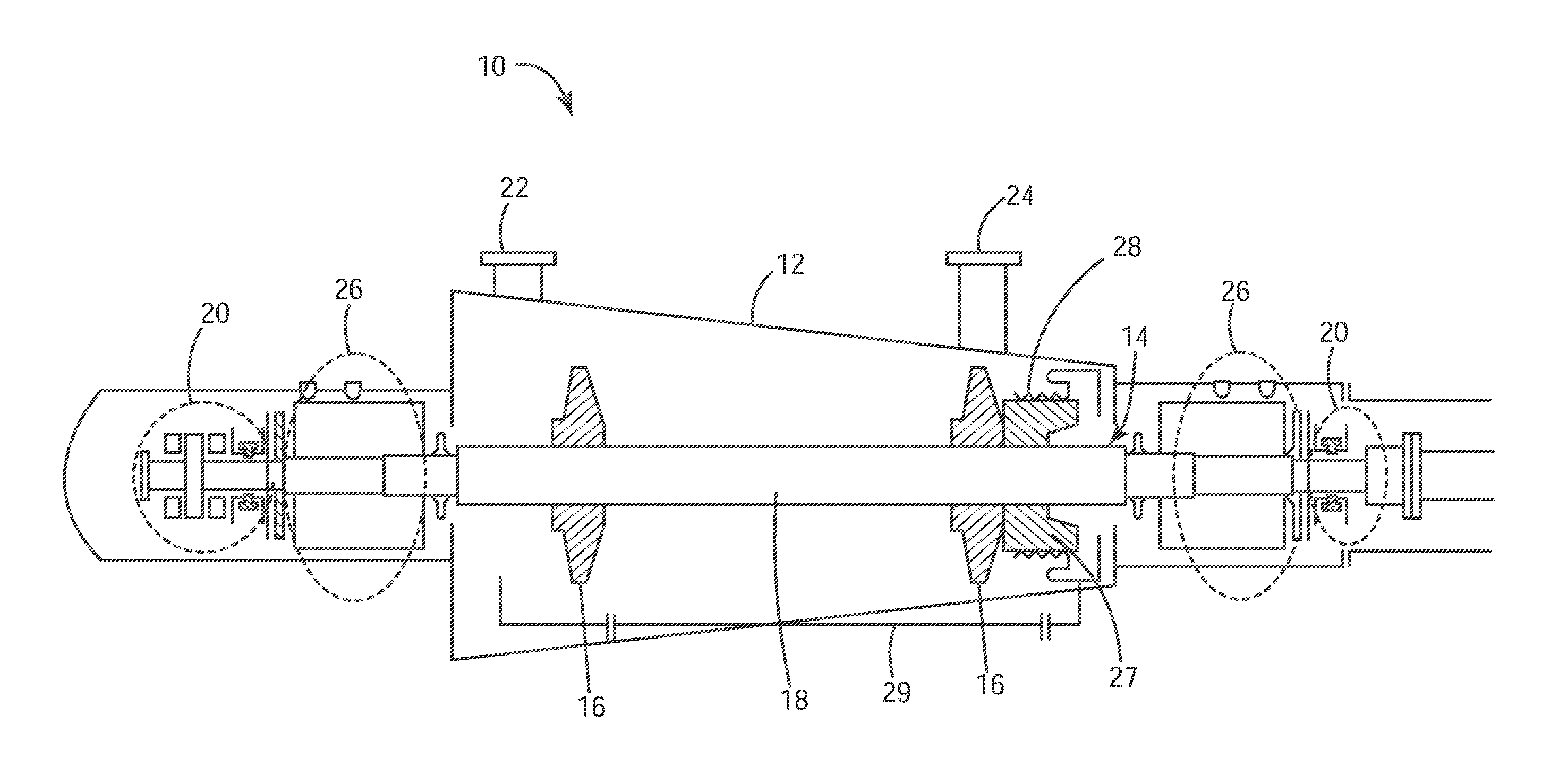
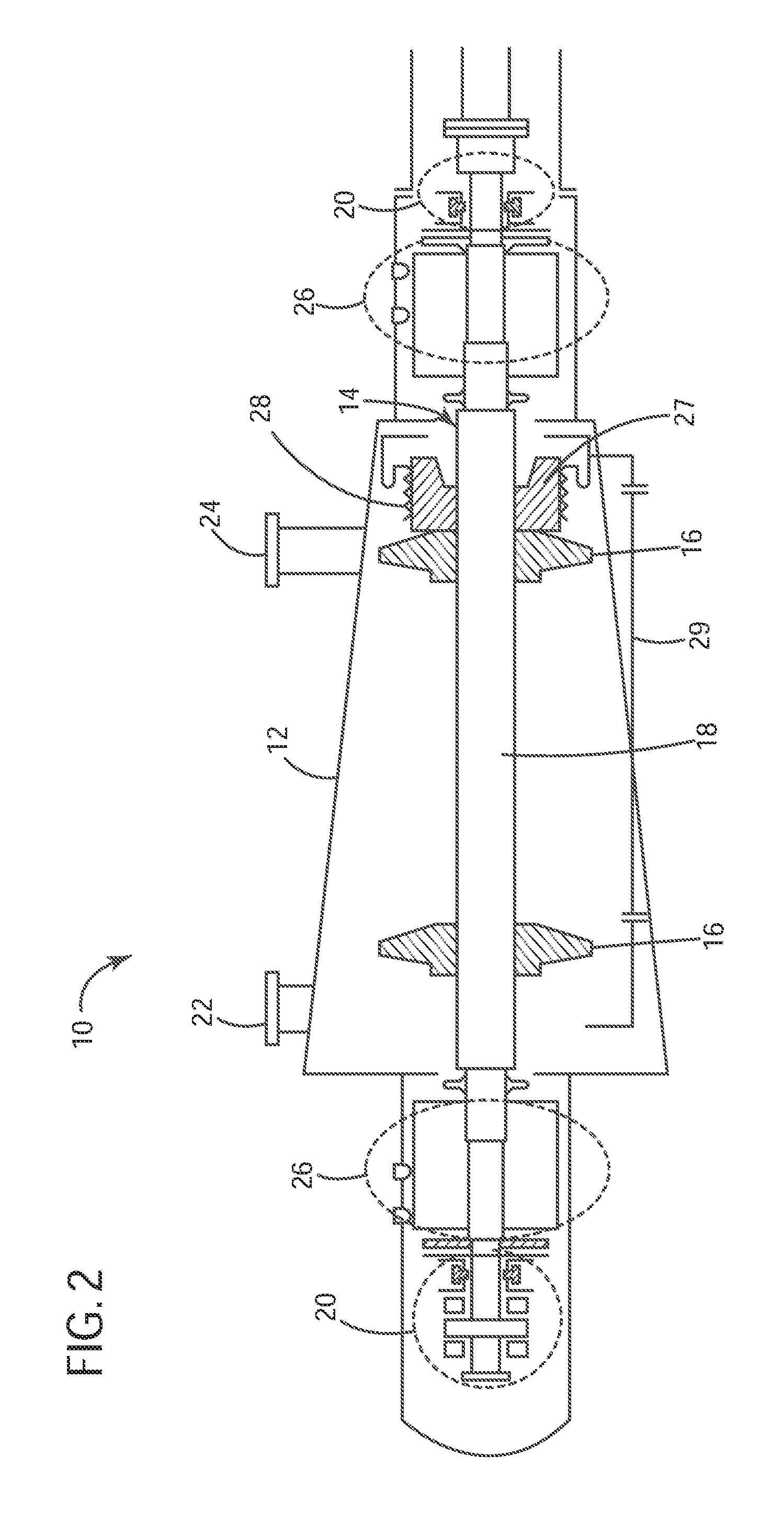
[0022]To provide some context for the subsequent discussion relating to sealing systems according to these exemplary embodiments, FIG. 2 schematically illustrates a multistage, centrifugal compressor 10 in which such sealing systems may be employed. Therein, the compressor 10 includes a box or housing (stator) 12 within which is mounted a rotating compressor shaft 14 that is provided with a plurality of centrifugal impellers 16. The rotor assembly 18 includes the shaft 14 and impellers 16 and is supported radially and axially through bearings 20 which are disposed on either side of the rotor assembly 18.

[0023]The multistage centrifugal compressor operat...


PUM


Abstract

Systems and methods according to these exemplary embodiments provide sealing mechanisms for centrifugal compressors. A sealing mechanism includes first, second and third dry gas seals arranged in series. Each seal receives its own sealing gas and has its own venting mechanism. Sealing gas pressures remain low enough that a dedicated compressor for supplying the sealing gases is not needed. Additionally, the risk of process gas being released into the atmosphere in case of seal failure is limited.

Description

CROSS REFERENCE TO RELATED APPLICATIONS[0001]This is a national stage application under 35 U.S.C. §371(c) of prior-filed, co-pending PCT patent application serial number PCT / EP2010 / 067456, filed on Nov. 15, 2010, which claims priority to Italian Patent Application Serial No. CO2009A000051, filed on Nov. 23, 2009, the entire contents of which are incorporated herein by reference.BACKGROUND OF THE INVENTION[0002]1. Field of the Invention[0003]Embodiments of the present invention relate generally to compressors and, more specifically, to the provision of dry gas seal systems in compressors.[0004]2. Description of the Prior Art[0005]A compressor is a machine which accelerates the particles of a compressible fluid, e.g., a gas, through the use of mechanical energy to, ultimately, increase the pressure of that compressible fluid. Compressors are used in a number of different applications, including operating as an initial stage of a gas turbine engine. Among the various types of compresso...

Claims


Application Information

Patent Timeline
IPC IPC(8): F01D25/16
CPCF01D25/22F04D29/122F01D25/16F16J15/3484F16J15/406F16J15/3404F04D29/12F01D11/06F16J15/34
Inventor MEUCCI, STEFANOSUSINI, PAOLO
Owner NUOVO PIGNONE SPA
Why Eureka
Try Eureka