Plow Blade Assembly

a technology of plow blades and assembly parts, which is applied in the direction of snow cleaning, way cleaning, construction, etc., can solve the problems of affecting the operation of equipment, affecting the service life of equipment, so as to improve the cleaning and/or removal action, improve the conformance to the substrate, and improve the effect of movability

Inactive Publication Date: 2013-07-11
KENNAMETAL INC
View PDF9 Cites 29 Cited by
  • Summary
  • Abstract
  • Description
  • Claims
  • Application Information

AI Technical Summary

Benefits of technology

[0007]In accordance with yet another aspect of the invention, an articulating blade for a plow blade assembly includes a first blade segment having a bottom surface for contacting a surface, the first blade segment further having a first angled chamfer formed on an end thereof. The articulating blade also includes a second blade segment adjacent the first blade segment also having a bottom surface for contacting the surface, wherein the second blade segment further has a second angled chamfer formed on an end thereof. The first angled chamfer and the second angled chamfer are structured and arranged for cooperating with each other to provide for variable degrees of movement of the first blade segment and the second blade segment relative to one another.
[0008]Advantageously, it will be appreciated that the plow blade assembly of the invention provides: for better conformance to a substrate, e.g., road surface to provide for better cleaning and / or removal action; for improved movability to avoid obstructions, reduce shock, and vibration and reduce damage to a road surface; and smaller blade sections for ease of installation and replacement, as well as improved ability to conform to the road surface.

Problems solved by technology

Steel blades have the advantage of being relatively inexpensive, but also the disadvantage of wearing out rapidly since the scraping operation can be a very abrasive operation.
Replacement of the steel blade is, of course, time consuming and represents downtime for the equipment.

Method used


Image

  • Plow Blade Assembly
  • Plow Blade Assembly
  • Plow Blade Assembly

Examples


Embodiment Construction

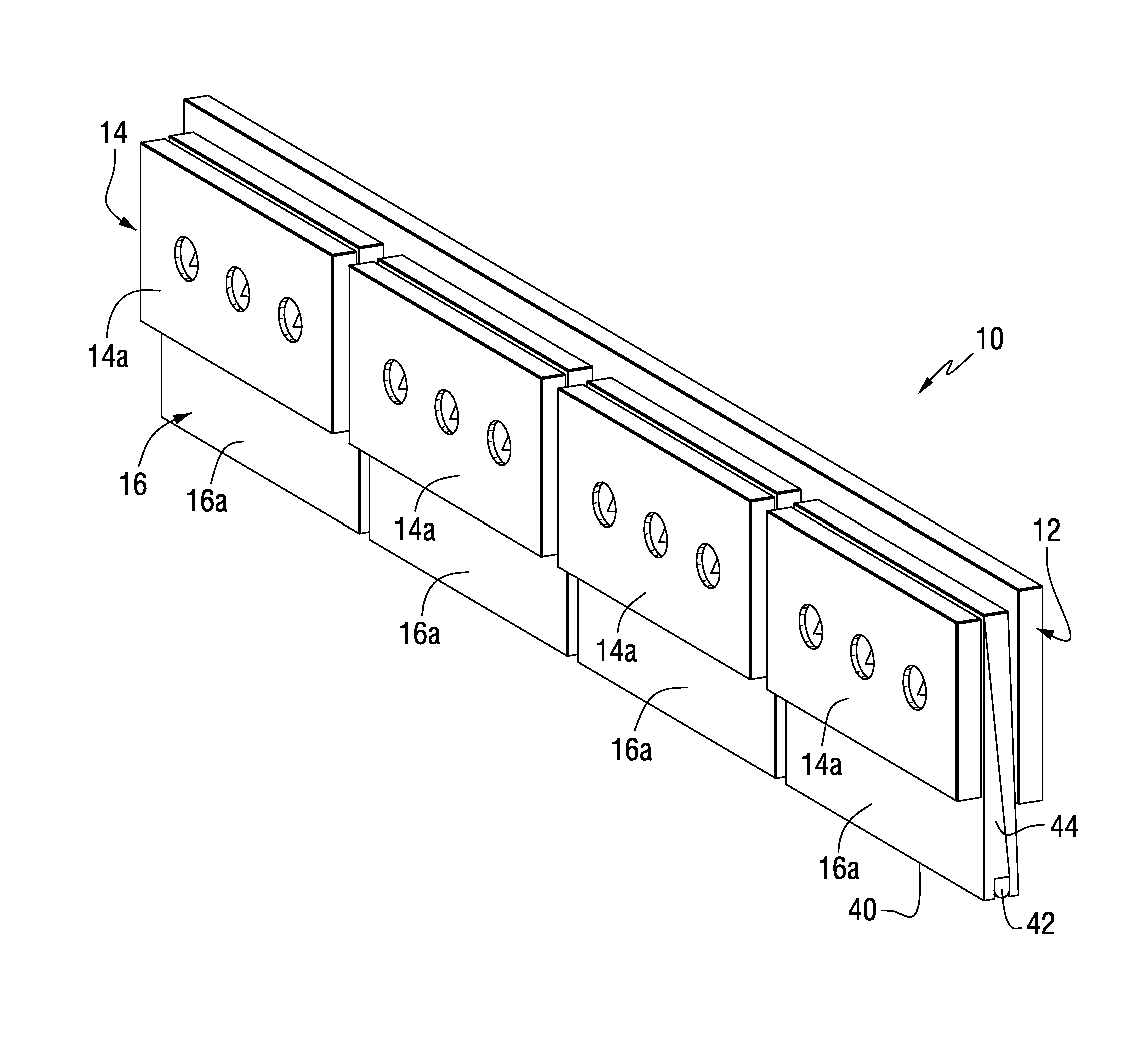
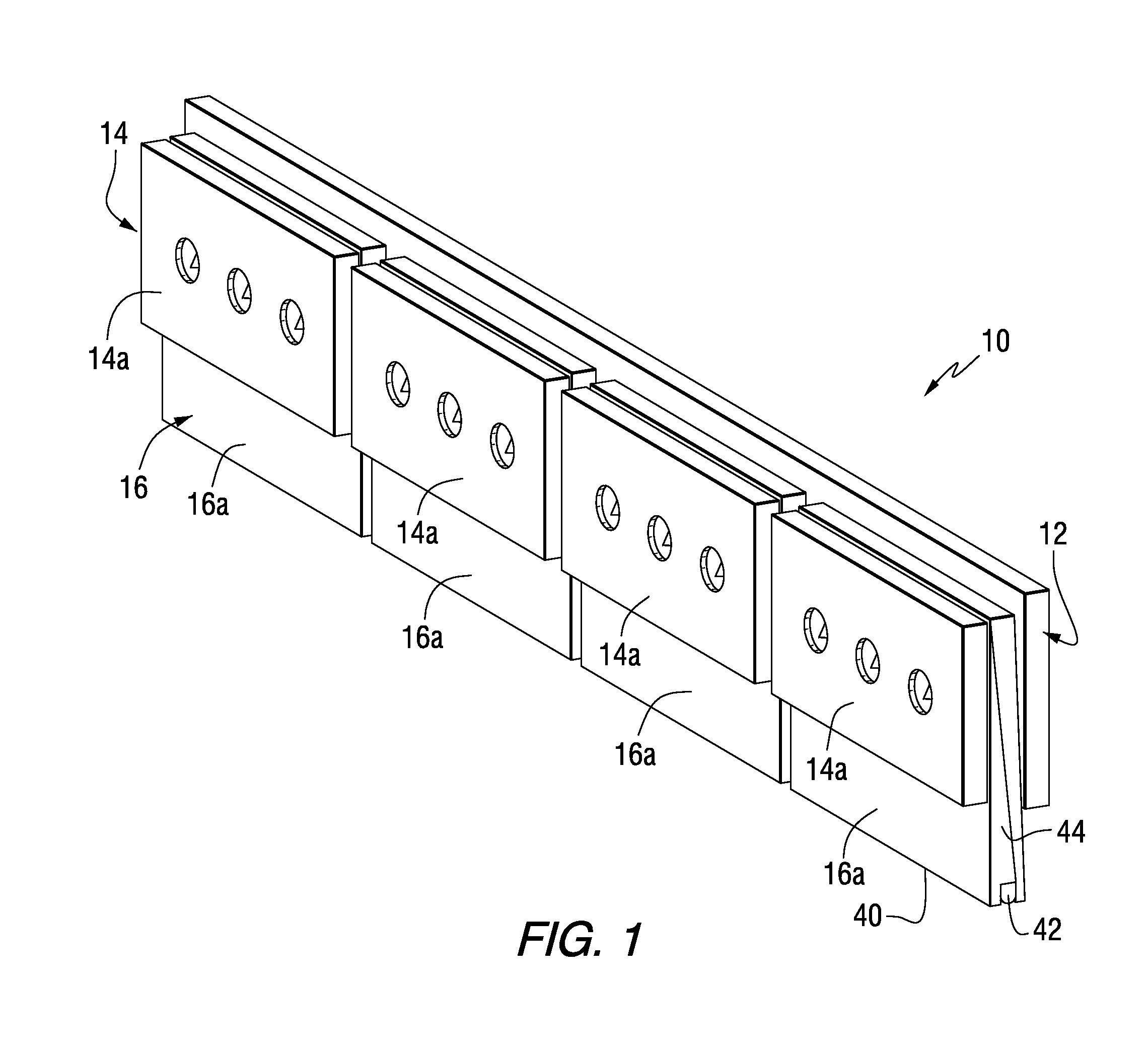
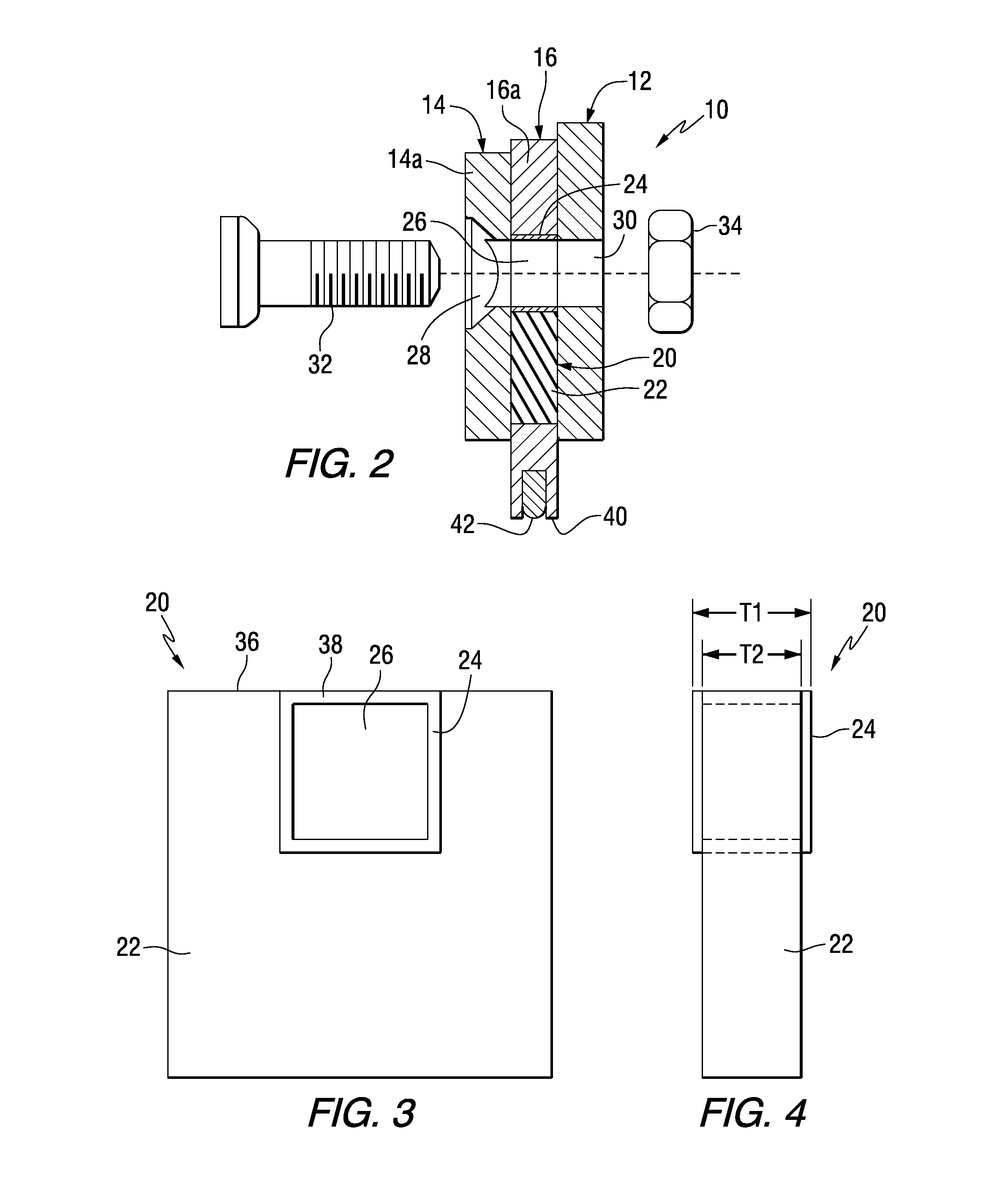
[0018]Referring to FIGS. 1 and 2, there is illustrated a plow blade assembly 10 in accordance with an aspect of the invention. The plow blade assembly 10 may be mounted on or used in association with a vehicle (not shown) for plowing or grading a surface, such as, for example, a road surface or earth strata.

[0019]Still referring to FIGS. 1 and 2, the plow blade assembly 10 includes a moldboard adapter plate 12, a cover plate 14, and a flexible or articulating blade 16 mounted between the moldboard adapter plate 12 and the cover plate 14. As best illustrated in FIG. 1, the moldboard adapter plate 12 may be a continuous member. The cover plate 14 may include multiple cover plate members 14a corresponding to multiple articulating blade segments 16a of the articulating blade 16. Thus, it will be appreciated that the components of the plow blade assembly 10, i.e., the moldboard adapter plate 12, the cover plate 14, and the articulating blade 16, may be provided in various configurations ...


PUM


Abstract

A plow blade assembly includes a moldboard adapter plate, a cover plate, and an articulating blade mounted between the moldboard adapter plate and the cover plate. The articulating blade includes a bushing assembly mounted therein, wherein the bushing assembly includes an elastomeric bushing and a non-elastomeric spacer non-centrally located in the elastomeric bushing. In one aspect, the non-elastomeric spacer is positioned adjacent a top edge of the elastomeric bushing.

Description

BACKGROUND OF THE INVENTION[0001]The invention pertains generally to a plow blade assembly for use in conjunction with snow plows and like vehicles, wherein the plow blade assembly travels over the surface of a substrate (e.g., the surface of a roadway) to remove snow and ice, as well as other debris and material, and provide for improved impact and performance properties.[0002]Snow plows are well known and carry a relatively-long moldboard which extends generally laterally (or across) of the substrate surface being worked by the blade. It is conventional practice to mount a snow plow blade, e.g., a cutting blade, on the lower edge of such moldboard with the blade, in turn, extending downwardly below the lower edge of the moldboard. The blade has a lower leading edge that forms the working surface of the blade. The vehicle carrying the blade then moves over the surface of the substrate in a direction generally perpendicular to the length of the moldboard. The blade then contacts or ...

Claims


Application Information

Patent Timeline
Patent Type & Authority Applications(United States)
IPC IPC(8): E01H5/06
CPCE01H5/063E01H5/06E01H5/061
Inventor DIEHL, TIMOTHY JAMESMANWAY, TERRY ALANROSS, STEPHEN MICHAELRAFFENSBERGER, PRESTON RUSSELLFOUSER, KENNETH DOUGLAS
Owner KENNAMETAL INC
Why Eureka
Try Eureka