

Amplifier for wireless receiver and associated method
- Summary
- Abstract
- Description
- Claims
- Application Information
AI Technical Summary
Benefits of technology
Problems solved by technology
Method used
Image

Examples
Embodiment Construction
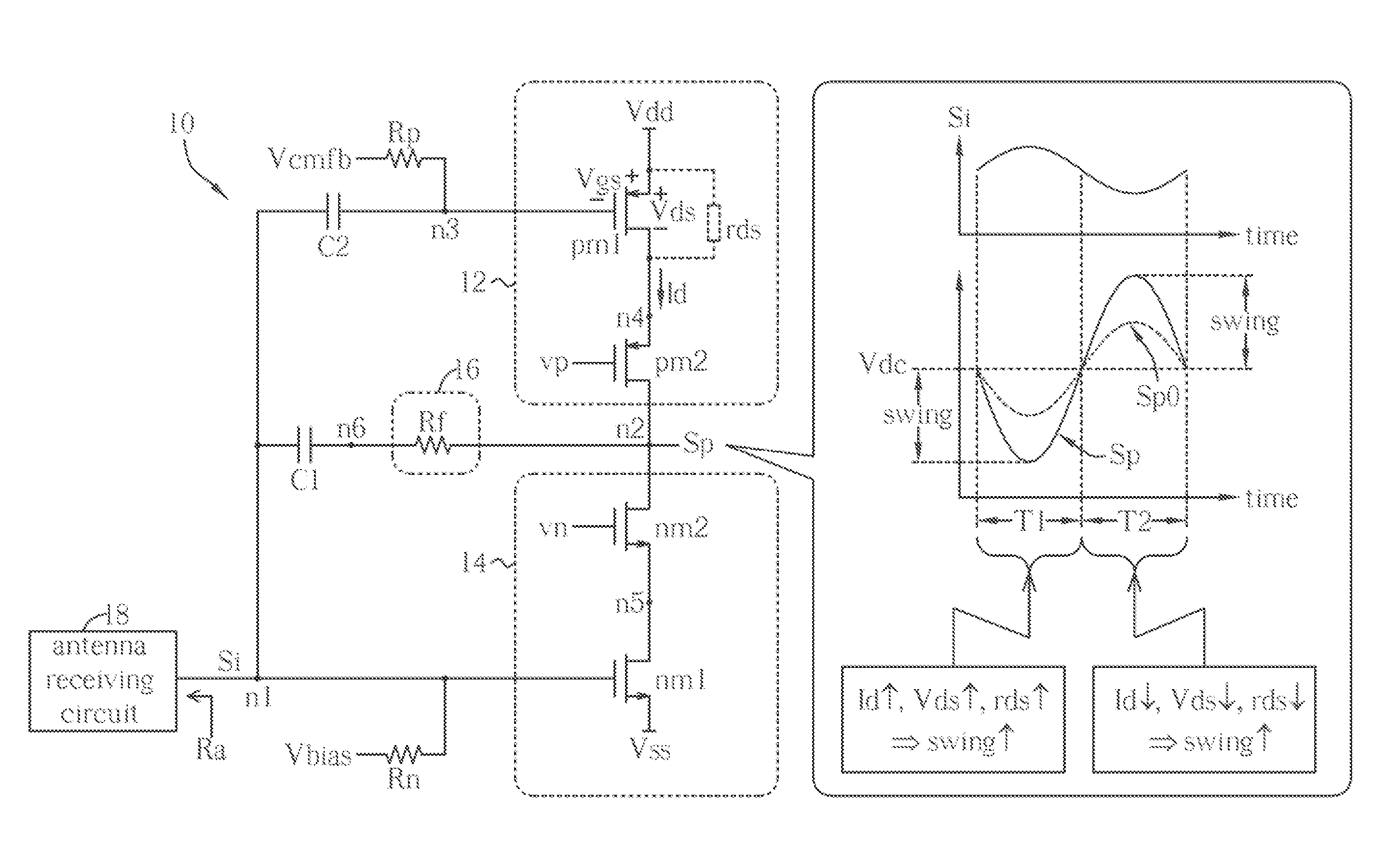
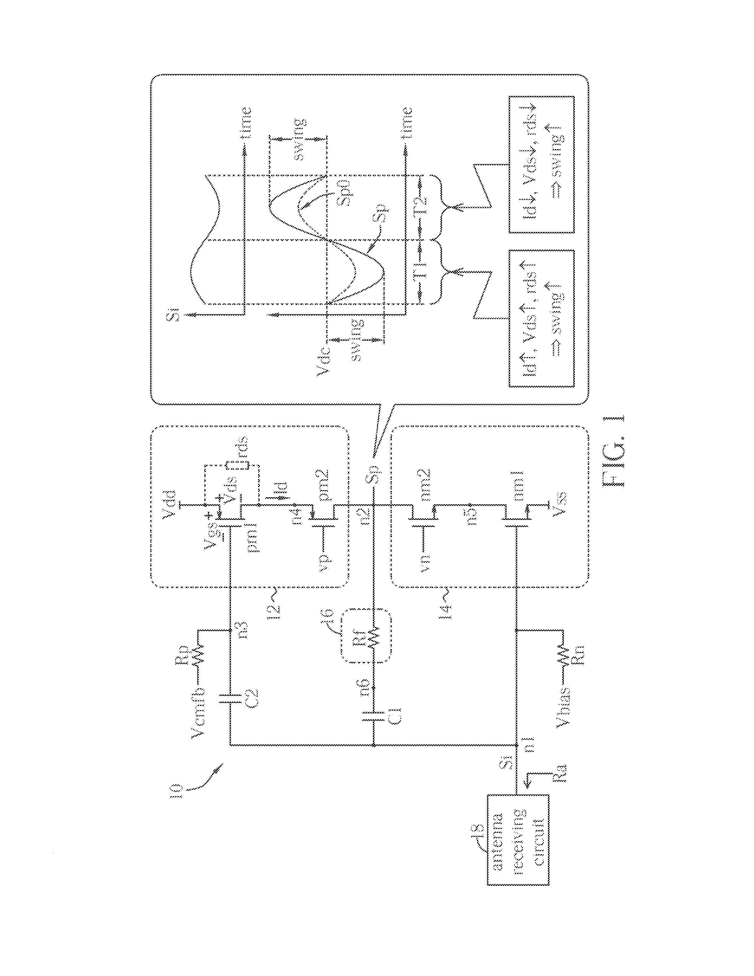
[0019]Please refer to FIG. 1 illustrating an amplifier 10 according to an embodiment of the invention. The amplifier 10 operates between supply voltages Vdd and Vss; with nodes n1 and n2 respectively as an input terminal and an output terminal. The amplifier 10 receives a signal Si (input signal) from the node n1 and provides a signal Sp (output signal) to the node n2 in response to the signal Si. The amplifier 10, e.g., an LNA, can be implemented in a wireless receiver where wireless signal is received as the signal Si by an antenna receiving circuit 18, and the signal Sp amplified by the amplifier 10 is then outputted to a mixer (not shown). The antenna receiving circuit 18 can include an antenna, transmission line(s), and associated passive and / or active elements, such as resistor(s), inductor(s), capacitor(s), external amplifier(s), filter(s), and / or SAW (surface acoustic wave) element(s). An impedance of the antenna receiving circuit 18 experienced by the amplifier 10 at the no...
PUM
 Abstract
Description
Claims
Application Information