
Smoke detection circuit, smoke detector comprising said circuit and alarm device comprising both the circuit and the detector

Active Publication Date: 2013-07-11
FINSECUR
View PDF6 Cites 13 Cited by
  • Summary
  • Abstract
  • Description
  • Claims
  • Application Information

AI Technical Summary

Benefits of technology

The patent text describes a new electronic smoke detection circuit design that improves sensitivity and reproducibility. By positioning the light emitter and receiver components at the same time, the circuit is simplified and the emitted light rays have consistent angles. The use of light reflectors is easier to produce, as they can be molded conjointly with the link connecting them. The design also avoids wasting polymer and eliminates a deflashing operation when mechanical parts are unmolded, resulting in cost savings.

Problems solved by technology

However, the positioning of these components, which is very difficult to realize and test, is the main cause of manufacturing faults in the detectors and imposes high manufacturing costs.
Faulty positioning can cause either a parasitic reflection blinding the receiver component or a reduction in sensitivity.
In addition, the positioning of these components is not very reproducible, reducing the ability to establish a precise specification for the smoke detectors that comprise them.
Lastly, the wires than connect these components to the printed circuit act as antennas collecting parasitic signals, thus reducing the detector's sensitivity.
However, in the proposed device the emitter comprises connecting wires to the printed circuit; this causes many drawbacks, for example, difficulty in correctly adjusting the angle between the emitted beams and the receiver's axis, the existence of an antenna effect towards the printed circuit likely to bring parasites to it, or the impossibility of properly defining the interaction zone.
Ultimately, a significant portion of the circuit production is rejected before the detector is assembled, even when it is not the complete detector that is rejected during a test.
In addition, the problem of positioning the emitter and receiver components makes it difficult to utilize surface-mounted components (“SMC”) since they are miniaturized and therefore more sensitive to faulty positioning.
However, the mechanical positioning of this radiation guide is still a problem and faulty positioning can lead to low sensitivity of the detector comprising two such radiation guides facing, respectively, an emitter and a receiver.
The mechanical assembly of two guides requires the realization of a complex, therefore costly, part in which parasitic rays can go from the emitter to the receiver and hamper detection.

Method used


Image

  • Smoke detection circuit, smoke detector comprising said circuit and alarm device comprising both the circuit and the detector
  • Smoke detection circuit, smoke detector comprising said circuit and alarm device comprising both the circuit and the detector
  • Smoke detection circuit, smoke detector comprising said circuit and alarm device comprising both the circuit and the detector

Examples


Embodiment Construction

[0065]For reasons of clarity, the figures are not to scale.

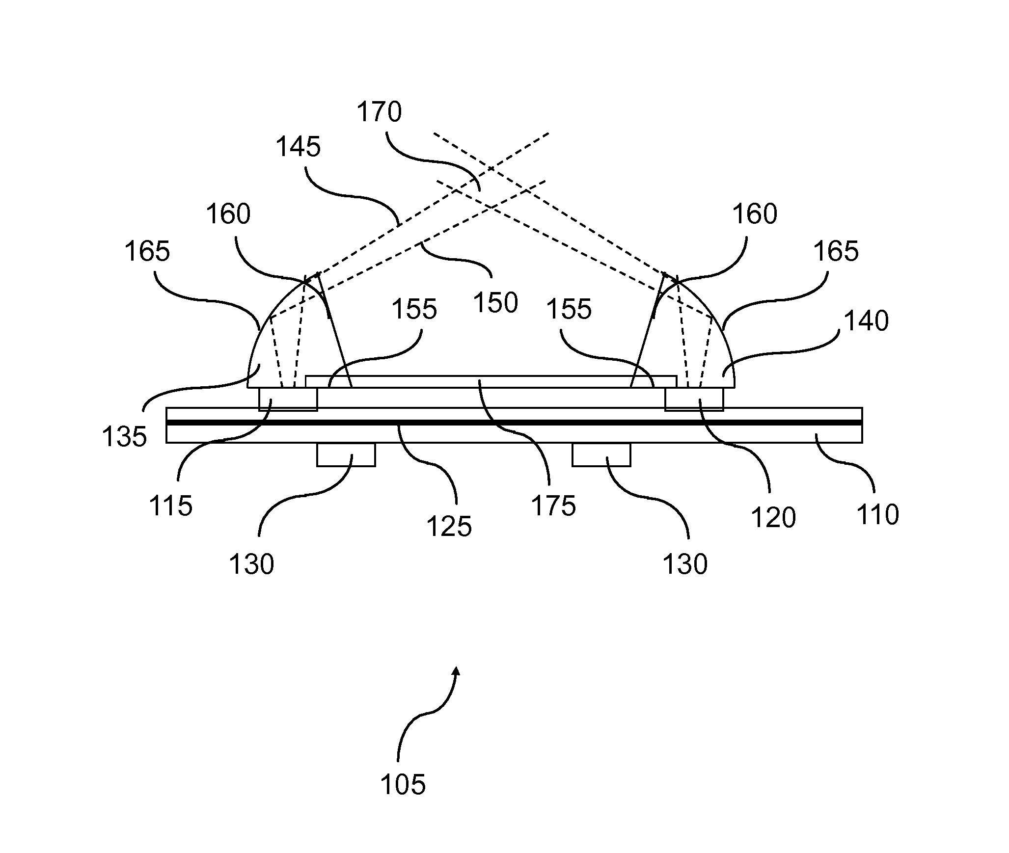
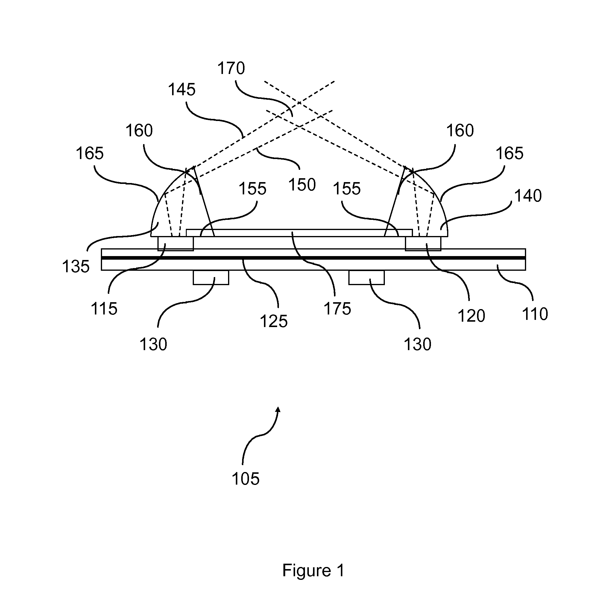
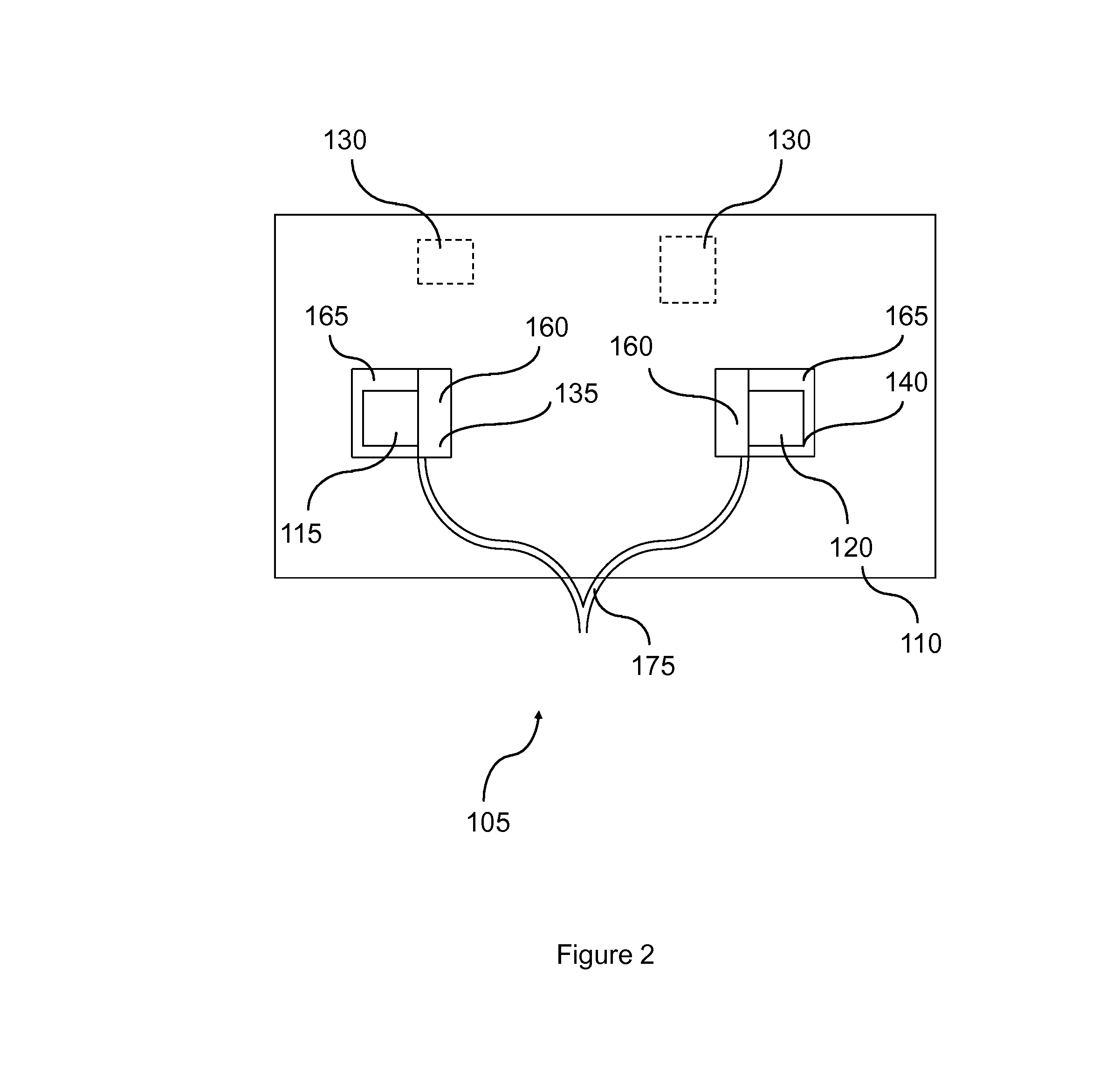
[0066]FIGS. 1 and 2 show a smoke detection circuit 105 comprising a printed circuit 110 bearing a light emitter component 115, a light receiver component 120, a ground plane 125 and supply and signal processing components 130. The printed circuit 110 is of known type and designed to bear surface-mounted components, SMCs. These components have the advantage of being able to be mounted and soldered automatically onto the printed circuit using automatic soldering machines. The SMC-type emitter and receiver have their optical axes substantially parallel to each other and substantially perpendicular to the printed circuit. The ground plane 125 is a metal plane inserted into the mass or on the surface of the printed circuit 110. In the embodiment described, this ground plane 125 forms a protection against electromagnetic emissions for at least the light receiver component 120.

[0067]Two light reflectors, formed here of the surfaces...


PUM

PropertyMeasurementUnit
Electrical resistanceaaaaaaaaaa
Areaaaaaaaaaaa
Wavelengthaaaaaaaaaa

Abstract

The optical scattering-based smoke detector comprises a scattering zone accessible to the smoke, a printed circuit forming a supporting member and a first and second light reflectors mounted on a common supporting member. An electronic smoke detection unit, a light emitter and a light receiver are mounted on the printed circuit. The receiver is sensitive to at least some of the wavelengths of the light rays emitted by the emitter. The first light reflector facing the emitter to direct the emitted light into a detection zone in the scattering zone. The second light reflector facing the receiver to direct, in the presence of smoke in the scattering zone, the scattered light from the detection zone onto the receiver. A single mechanical part comprises the first and second light reflectors and a link resistant to the passage of the light from the first light reflector to the second light reflector.

Description

RELATED APPLICATIONS[0001]This application is a §371 application from PCT / FR2011 / 052102 filed Sep. 14, 2011, which claims priority from French Patent Application No. 1057338 filed Sep. 14, 2010, each of which is herein incorporated by reference in its entirety.TECHNICAL FIELD OF INVENTION[0002]This invention concerns a smoke detection circuit, a smoke detector comprising said circuit and an alarm device comprising both the circuit and the detector. It applies, in particular, to detecting smoke in residential, industrial commercial or recreational buildings and public or private works structures.BACKGROUND OF THE INVENTION[0003]Many smoke detectors are known. The principle of an optical scattering-based smoke detector, for example, is based on utilizing, firstly, an emitter of light rays and, secondly, a receiver of light signals scattered by the ambient air. When there is no smoke in the air that enters the detector, the receiver only receives a very small amount of the scattered li...

Claims


Application Information

Patent Timeline
IPC IPC(8): G01N21/53
CPCG01N21/53Y10T29/4913G08B29/043G08B17/107G08B17/113
Inventor PICHARD, LAURENTDI MARCO, STEPHANE
Owner FINSECUR
Learn More