Screw turbine and method of power generation

a technology of screw turbine and blade, which is applied in the direction of propellers, propulsive elements, water-acting propulsive elements, etc., can solve the problems of limit the efficiency that may be obtained using existing water turbines, and achieve the effect of facilitating blade rotation

Inactive Publication Date: 2013-07-11
WEBBER GREGORY MARK
View PDF13 Cites 4 Cited by
  • Summary
  • Abstract
  • Description
  • Claims
  • Application Information

AI Technical Summary

Benefits of technology

[0024]The helical turbine blade may be mounted by any suitable means. For example, the blade may be mounted on a structure that is constructed in a body of water (i.e. secured within the river bed), or may be mounted at the distal end of an arm secured to and extending from, for

Problems solved by technology

Even so, there are limits to the efficiency tha

Method used


Image

  • Screw turbine and method of power generation
  • Screw turbine and method of power generation
  • Screw turbine and method of power generation

Examples


Embodiment Construction

[0037]The invention will now be described in more detail with reference to the accompanying drawings. It should be appreciated that the following is provided by way of exemplification only and should not be construed as limiting on the invention in any way. In the drawings:

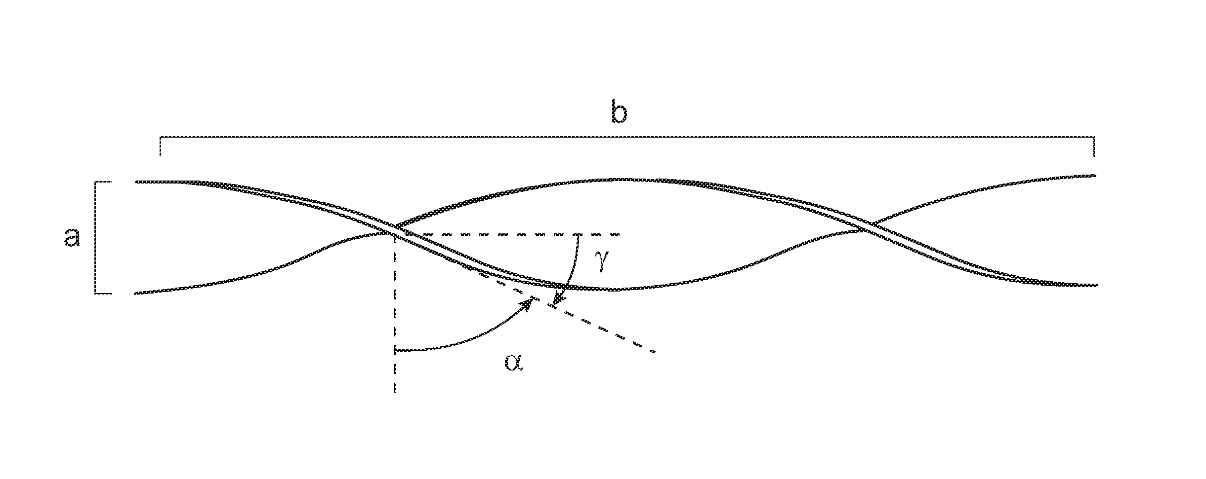
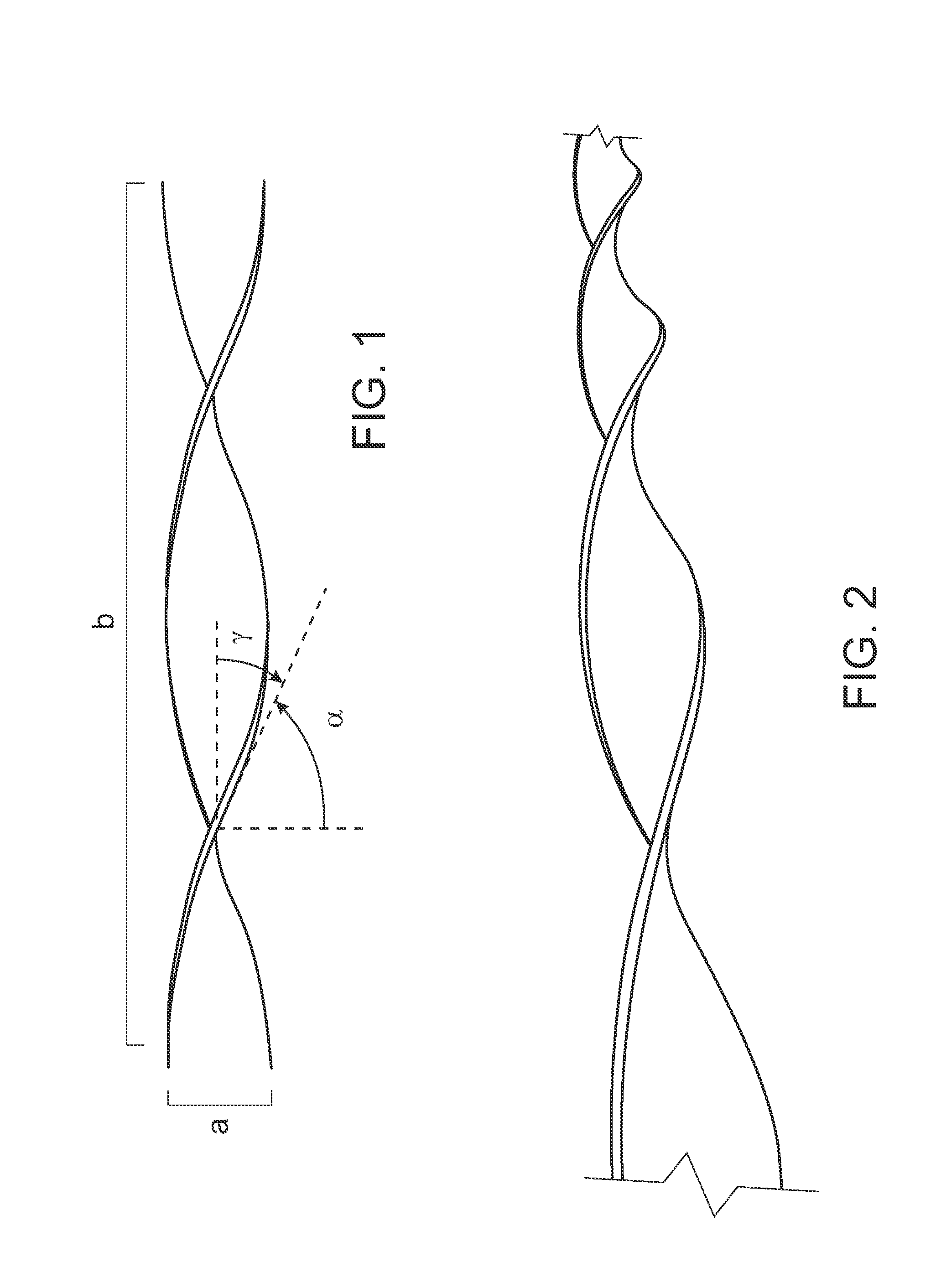
[0038]FIG. 1 illustrates a side view of a helical turbine blade; and

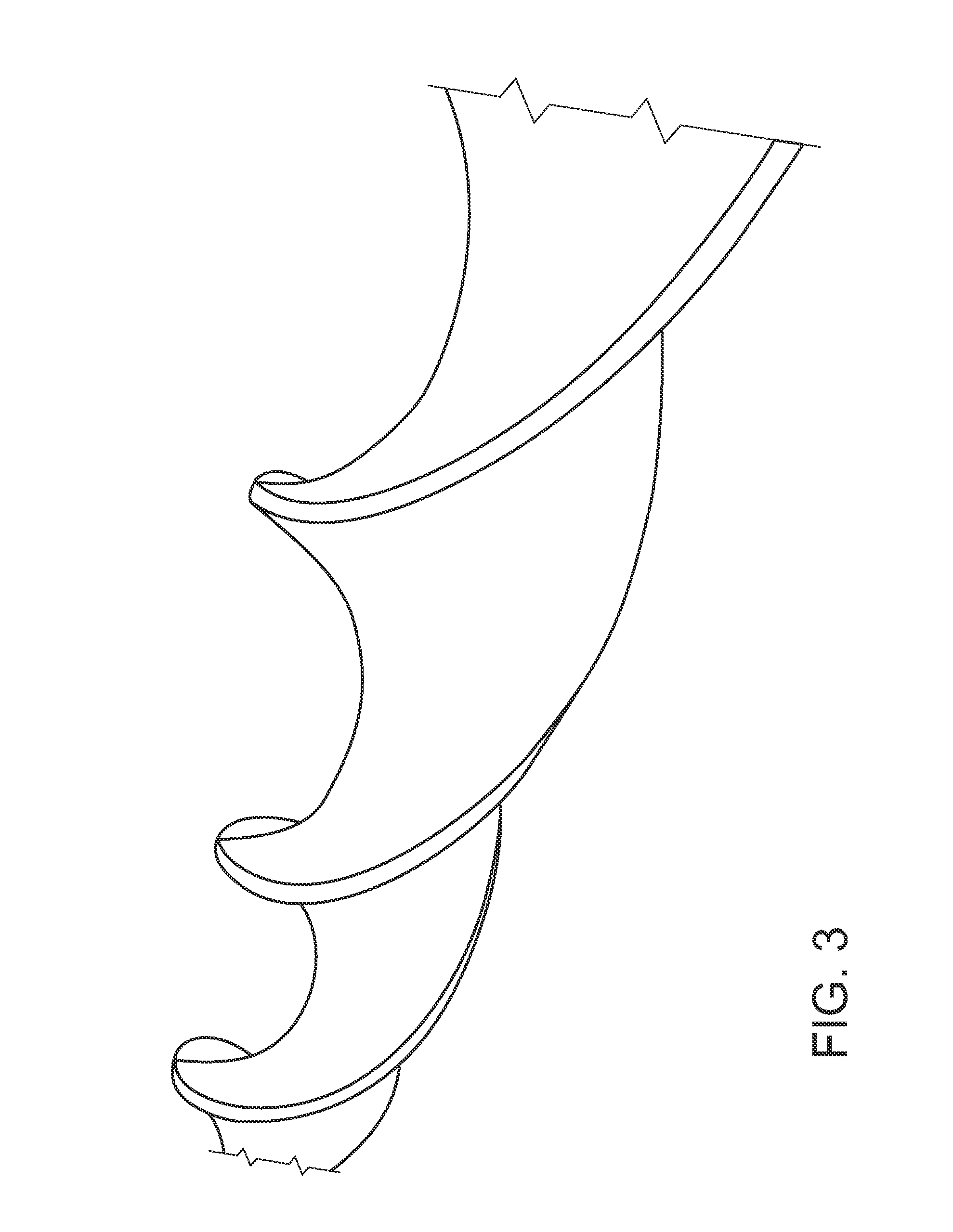
[0039]FIGS. 2 and 3 illustrate perspective views of a helical turbine blade.

[0040]Referring to the figures, the helical turbine blade takes the form of an axleless helix. Effectively, the helical turbine blade is constituted by a strip of material, for example steel or other suitable material, which is twisted along its length. The twists are relatively gentle, and therefore the helix angle y relatively small. Consequently, the lead angle a is relatively large. This is particularly the case compared with conventional screw turbines, the blades of which are generally provided with a much greater degree of raking.

[0041]The diameter “a” of the helica...


PUM


Abstract

A screw turbine comprising a helical turbine blade mounted for axial rotation, a mount associated with the helical turbine blade and mounting the helical turbine blade for axial rotation, and a generator associated with the helical turbine blade which converts energy imparted to the helical turbine blade to electricity, wherein the diameter of the helical turbine blade is less than the lead of the helical turbine blade and wherein said screw turbine is adapted to permit lateral exchange of fluid in use.

Description

[0001]CROSS-REFERENCE TO RELATED PATENT APPLICATIONS[0002]This patent application is a continuation of PCT / AU2011 / 000983, filed Aug. 3, 2011, which claims priority to Australian Application No. 2010903459, filed Aug. 3, 2010, the entire teachings and disclosure of which are incorporated herein by reference thereto.FIELD OF THE INVENTION[0003]The present invention relates to a screw turbine and method of power generation which employs same. Particularly, the invention relates to an Archimedean screw turbine including a helical turbine blade which has a relatively small helix angle and which, in use, advantageously does not require or employ an outer sheath that houses it.BACKGROUND TO THE INVENTION[0004]Various forms of turbines are known. These include, for example, cross-flow turbines, Kaplan turbines and Archimedean screw turbines.[0005]In the cross-flow turbine a cylindrical water wheel or runner with a horizontal shaft is provided. The wheel or runner includes a number of blades...

Claims


Application Information

Patent Timeline
IPC IPC(8): F03B3/12F01D5/14F04D29/38
CPCF03B3/08F03B17/00F05B2240/243F01D5/141Y02E10/223Y02E10/20
Inventor WEBBER, GREGORY MARK
Owner WEBBER GREGORY MARK
Why Eureka
Try Eureka