Detection of over-current in a battery pack

a battery pack and over-current technology, applied in the direction of mechanical power/torque control, emergency protective arrangements for limiting excess voltage/current, electric devices, etc., can solve the problem that electric vehicles may only be able to sustain operation at their maximum current, and most short-circuit protection devices have a very short thermal time constant, etc. problems, to achieve the effect of reducing risks and reducing risks

Active Publication Date: 2013-07-11
TESLA INC
View PDF0 Cites 44 Cited by
  • Summary
  • Abstract
  • Description
  • Claims
  • Application Information

AI Technical Summary

Benefits of technology

[0008]Regarding responding to a detected non-fusing over-current internal short in a battery pack, a system and method are disclosed. A microprocessor-implemented response system for an over-current internal short in an battery pack includes an evaluator monitoring an over-current internal short flag indicative of a possible over-current internal short within a plurality of electrically-serially-coupled battery elements storing energy for the battery pack; and a remediation system, coupled to the battery elements and responsive to the possible over-current internal short flag when the evaluator detects a likelihood of the possible over-current internal short, to decrease risks associated with the possible over-current internal short ...

Problems solved by technology

The battery packs are designed to provide high levels of safety and stability, yet situations can arise where a portion of a battery pack experiences a local thermal condition which generates significant heat.
When the temperature is great enough and sustained, the local thermal condition can transform into a runaway thermal condition affecting wide areas of the battery pack, and sometimes the entire battery pack under certain circumstances.
Most short circuit protection devices have a very short thermal time constant and are only effective above a predetermined current.
However, an electric vehicle may only be capable of sustaining operation at its maximum current for a short perio...

Method used


Image

  • Detection of over-current in a battery pack
  • Detection of over-current in a battery pack
  • Detection of over-current in a battery pack

Examples


Embodiment Construction

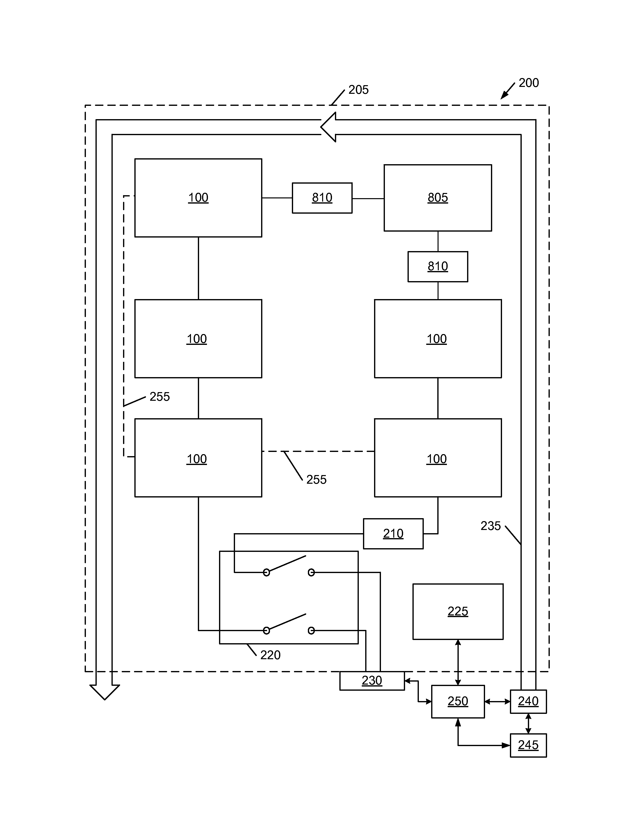
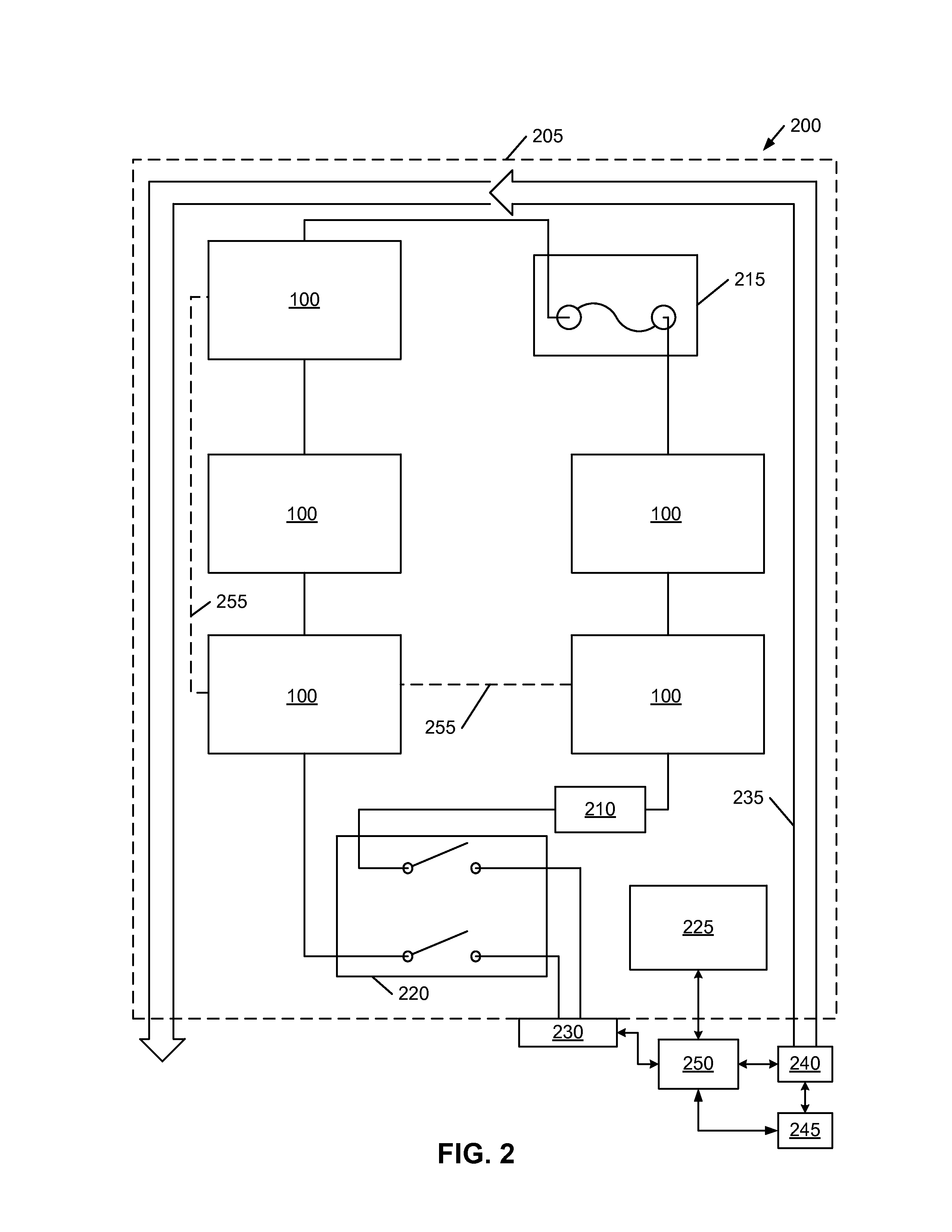
[0024]Embodiments of the present invention provide an apparatus and method providing to detecting and responding to potentially hazardous over-current due to internal short circuit to limit possible excessive thermal conditions of the individual battery cells and modules. The following description is presented to enable one of ordinary skill in the art to make and use the invention and is provided in the context of a patent application and its requirements.

[0025]Various modifications to the preferred embodiment and the generic principles and features described herein will be readily apparent to those skilled in the art. Thus, the present invention is not intended to be limited to the embodiment shown but is to be accorded the widest scope consistent with the principles and features described herein.

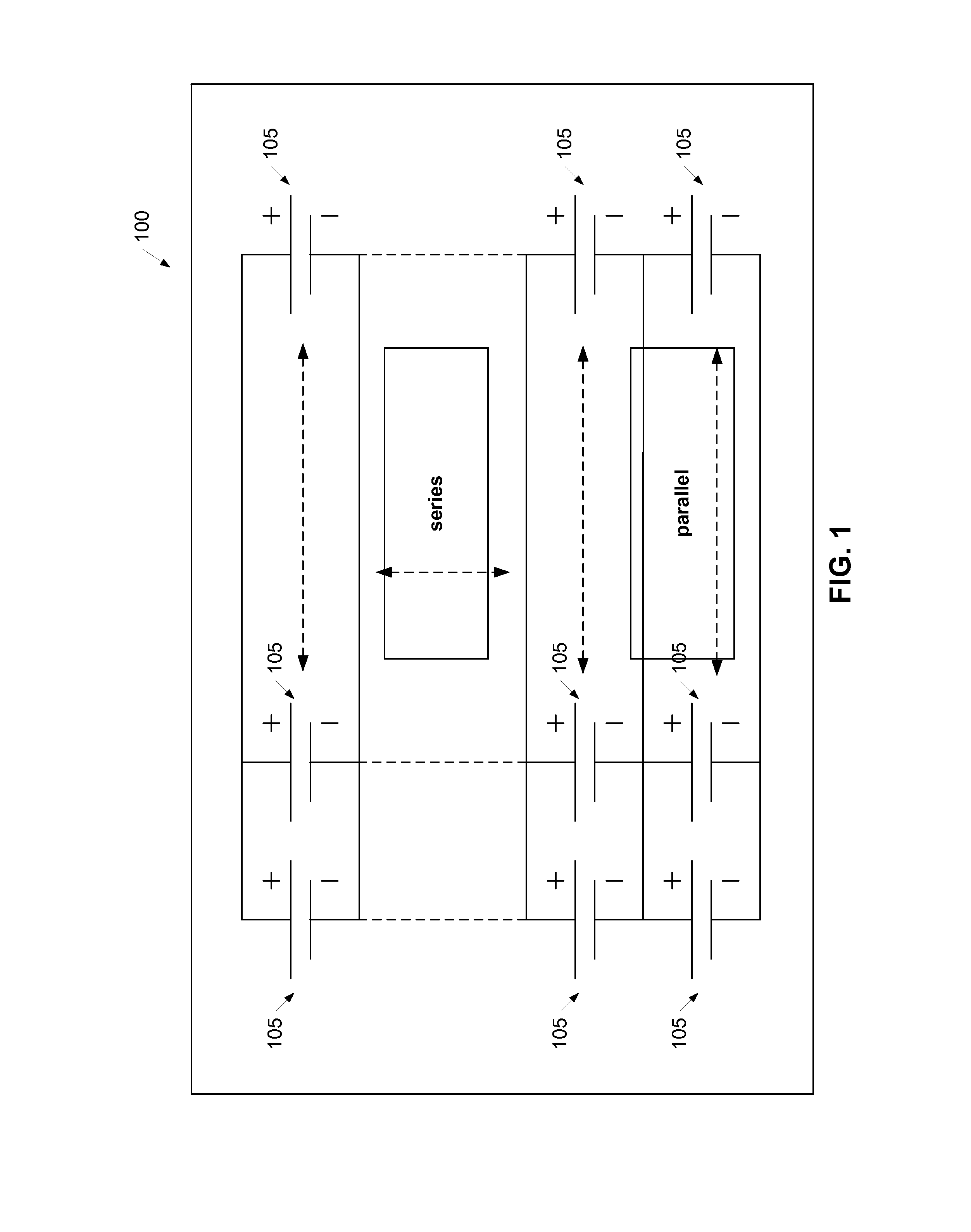
[0026]FIG. 1 illustrates an exemplary battery module 100 having a collection of parallel and / or series connected battery cells 105. Battery module 100 design may include a few to 100's of...


PUM


Abstract

A controller identifies a condition of a hazardous internal short by comparing patterns of series element voltages to the last known balance condition of the series elements. If the loaded or resting voltage of one or more contiguous series elements uniformly drop from the previously known condition by an amount consistent with an over-current condition, an over-current internal short circuit fault is registered. The desired response is to prevent the affected series elements from heating to a hazardous temperature by summoning the maximum heat rejection capability of the system until the short ceases and the affected elements cool, the cooling function is no longer able to operate due to low voltage, or the affected series string has drained all of its energy through the short. Also includes are responses that allow the battery pack to continue to power the cooling system even though it may enter an over-discharged state.

Description

BACKGROUND OF THE INVENTION[0001]The present invention relates generally to detection of and response to potentially hazardous conditions in an electric vehicle battery pack, and more particularly but not exclusively, to detecting and responding to potentially hazardous over-current due to internal short circuit to limit possible excessive thermal conditions of the individual battery cells and modules.[0002]Many high-performance energy storage solutions now employ series-connected modules that, in turn, are series and parallel combinations of individual battery cells. Battery packs used with electric vehicles store large amounts of energy in a small space, producing high energy densities. The battery packs are designed to provide high levels of safety and stability, yet situations can arise where a portion of a battery pack experiences a local thermal condition which generates significant heat. When the temperature is great enough and sustained, the local thermal condition can trans...

Claims


Application Information

Patent Timeline
IPC IPC(8): G06F7/00G05D23/00G06F1/26G06F19/00
CPCB60L3/0046B60L11/1859B60L11/1866B60L11/1874B60L2240/545B60L2240/547Y10S903/907H01M10/441H01M10/482H01M2220/20Y02T10/7005Y02T10/7061H01M10/5004B60L2240/549B60L58/14B60L58/22B60L58/26B60L58/15B60L58/13B60L58/18Y02T10/70Y02E60/10H01M10/60
Inventor HERMANN, WESTON ARTHURKOHN, SCOTT IRA
Owner TESLA INC
Why Eureka
Try Eureka