

Parallel foamed coaxial cable
- Summary
- Abstract
- Description
- Claims
- Application Information
AI Technical Summary
Benefits of technology
Problems solved by technology
Method used
Image

Examples
embodiment
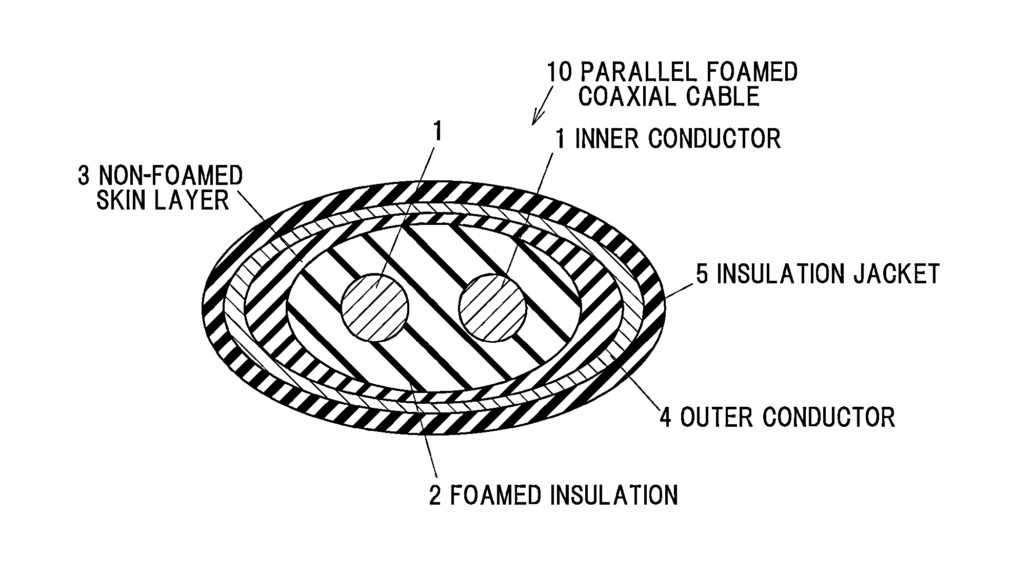
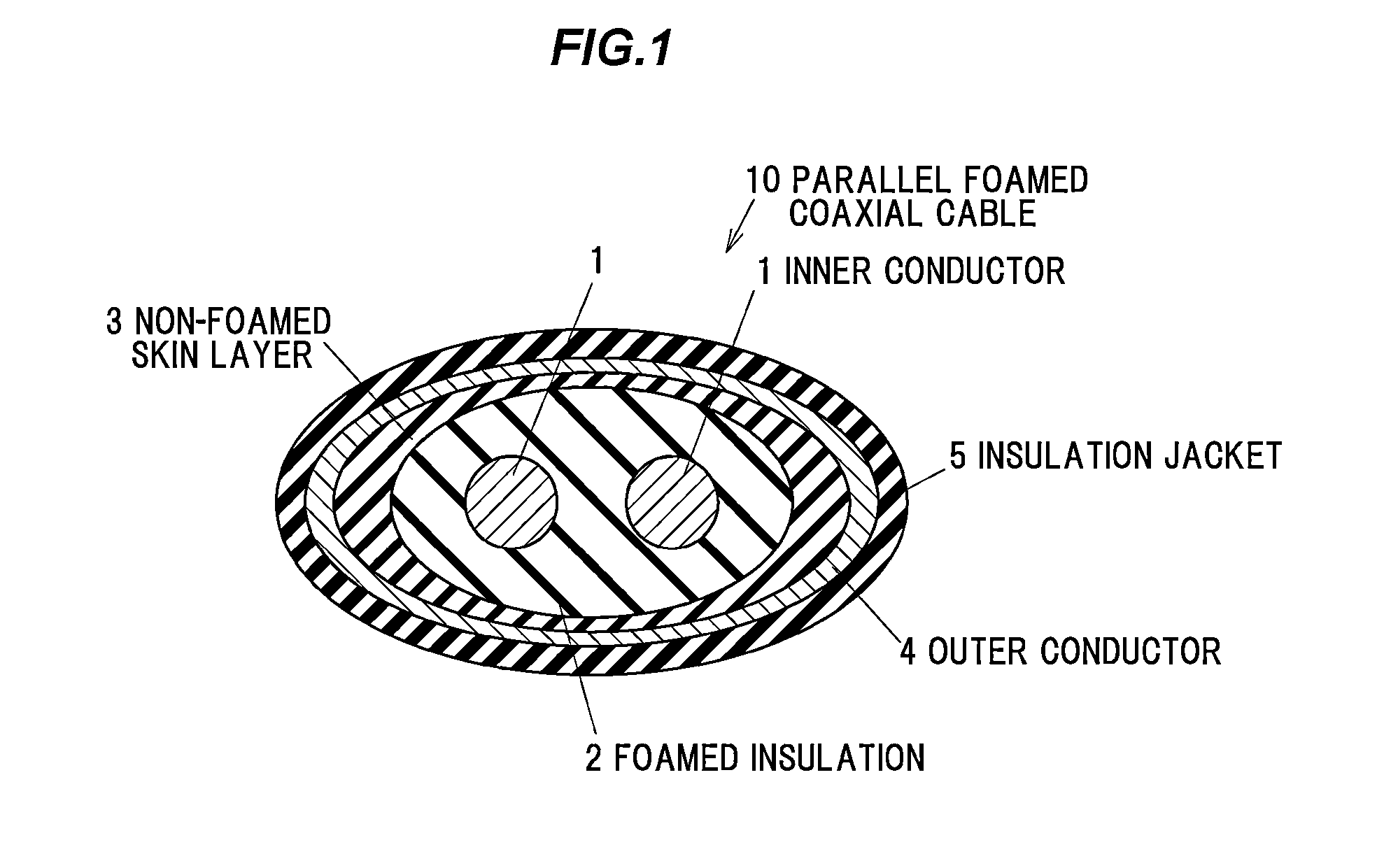
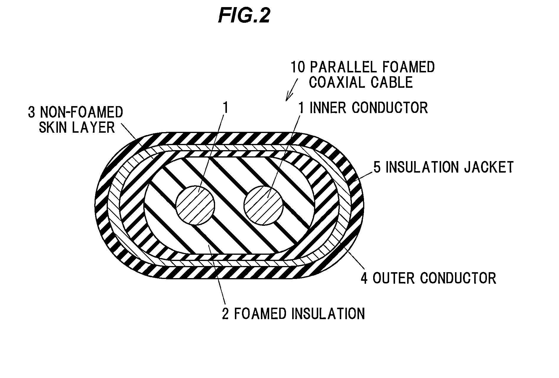
[0042]As shown in FIGS. 1 and 2, a parallel foamed coaxial cable 10 in the present embodiment is provided with one or more pairs (one pair in FIGS. 1 and 2) of inner conductors 1 arranged side by side and extending in parallel, a foamed insulation 2 arranged to cover the inner conductors 1 all together and having a cross section in an elliptical shape, a rounded-rectangular shape or a quasi-elliptical shape formed by combining plural curved lines, a non-foamed skin layer 3 arranged to cover the foamed insulation 2 and having the maximum thickness present in a major axis direction of the cross section of the foamed insulation 2 and the minimum thickness present in a minor axis direction of the cross section of the foamed insulation 2, an outer conductor 4 arranged to cover the non-foamed skin layer 3 and an insulation jacket 5 arranged to cover the outer conductor 4.
[0043]As described above, in the parallel foamed coaxial cable 10 of the present embodiment, one or more pairs of inner...
example 1
[0083]The constituent materials shown in Table 1 were used. That is, a silver-plated copper wire (product name: 24AWG (0.511 mm in diameter), from Sanshu-Densen KK) was used as an inner conductor, 50 parts by mass of high-density polyethylene (product name: 6944, from Dow Chemical Co.), 50 parts by mass of low-density polyethylene (product name: B028, from Ube Industries, Ltd.) and 1 part by mass of nucleating agent (product name: ADCA, from Eiwa Chemical Ind. Co., Ltd.) were used as the foamed insulation, high-density polyethylene (product name: 6944, from Dow Chemical Co.) was used as the non-foamed skin layer and a copper tape (15 μm in thickness, including 6 μm of PET) was used as an outer conductor.
[0084]The extrusion conditions are shown in Table 2. That is, when a foamed insulation was made by a chemical foaming method at a screw speed fixed at 20 rpm and a cylinder temperature fixed at 220° C. (without gas injection), a foamed insulation having the foaming degree of about 55...
PUM
 Abstract
Description
Claims
Application Information