
Cold crucible induction melter integrating induction coil and melting furnace

Active Publication Date: 2013-07-18
KOREA HYDRO & NUCLEAR POWER CO LTD
View PDF15 Cites 5 Cited by
  • Summary
  • Abstract
  • Description
  • Claims
  • Application Information

AI Technical Summary

Benefits of technology

The present invention is related to a cold crucible induction melter (CCIM) which is an apparatus used for melting materials such as ceramic or metal. The invention simplifies the structure of the CCIM and improves energy efficiency by excluding the water cooled segment and allowing the induction coil to serve as a water cooled segment simultaneously. The induction coil is disposed in a sloped structure towards the discharge direction of the molten material and is detachably and attachably around the molten material discharge hole. This enhances the generation efficiency of an induced current in the discharged molten material and allows for smooth discharging of high melting point materials.

Problems solved by technology

However, the existing CCIMs are disadvantageous in that the water cooled segments positioned inside the induction coils consume a lot of electrical energy.
Also, in the case of the existing CCIMs, the induction coils are mostly installed horizontally and designed to mainly focus on the melting of molten materials, but they do not include a function to facilitate discharge of the molten materials.
However, the CCIMs employing the above principle have a problem in that since the temperature of the molten material is lowered while the molten material is discharged, ceramics or metals having a high melting point may be partially solidified and thus flowability is reduced to not smoothly discharge the molten material.
However, this method has a limitation in discharging metals (e.g., a group of noble metals, etc.) having a higher melting point than the Inconel tube.

Method used


Image

  • Cold crucible induction melter integrating induction coil and melting furnace
  • Cold crucible induction melter integrating induction coil and melting furnace
  • Cold crucible induction melter integrating induction coil and melting furnace

Examples


Embodiment Construction

[0026]Hereinafter, configuration and operation of a cold crucible induction melter according to a preferred embodiment of the present invention will be described in detail with reference to the accompanying drawings.

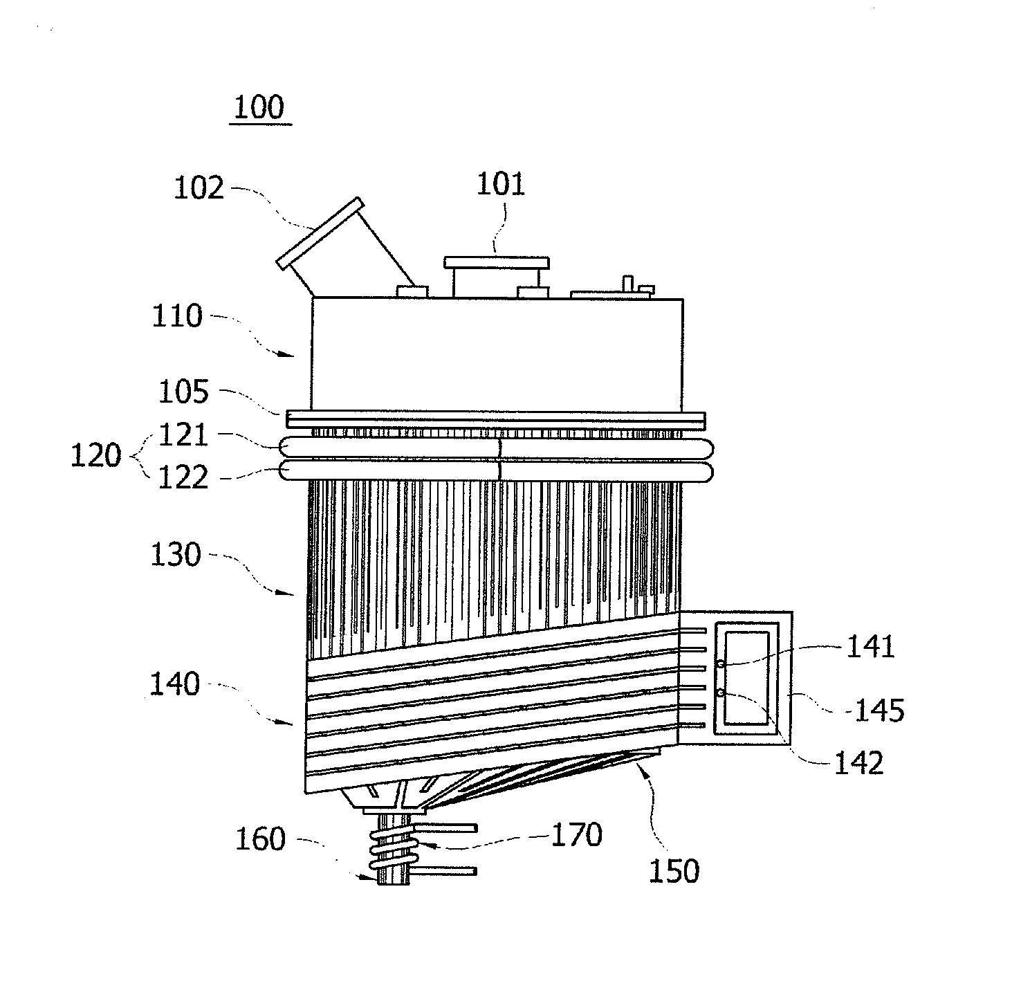
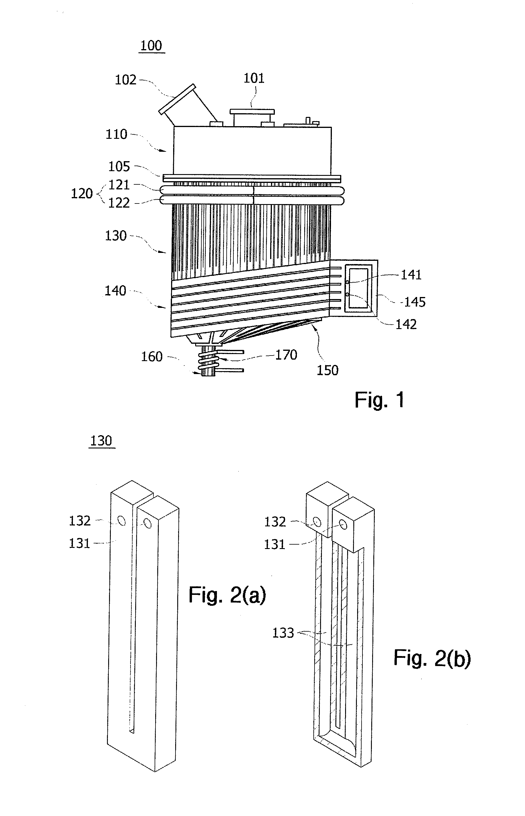
[0027]FIG. 1 is an overall schematic view of a cold crucible induction melter integrating an induction coil and a melting furnace according to the present invention.

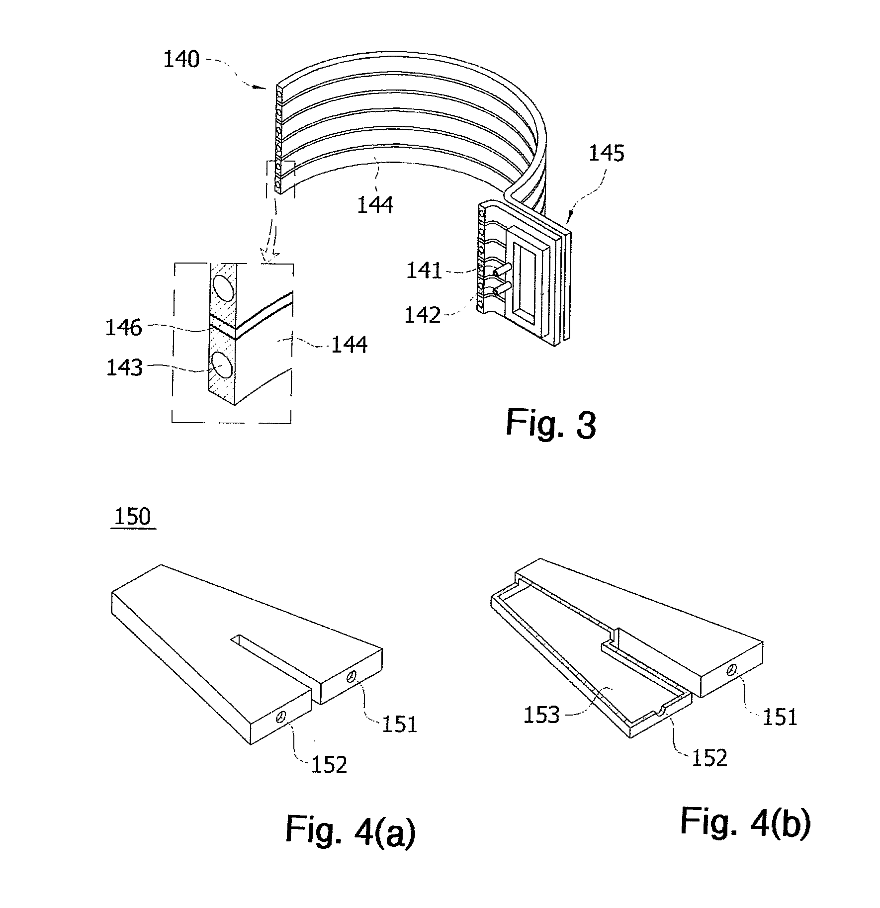
[0028]The cold crucible induction melter 100 integrating an induction coil and a melting furnace according to the present invention includes an upper chamber 110 provided with a waste inlet 101 in which a melting target material, such as radioactive waste, general industrial waste, ceramic materials, metal materials, or the like is put, and an off-gas outlet 102 through which an off-gas generated during melting is discharged, and a lower chamber disposed under the upper chamber 110, and connected to the upper chamber 110 by a joint 105 disposed therebetween, in which the put waste is received, molten and disc...


PUM


Abstract

A cold crucible induction melter includes an induction coil and a melting furnace. The induction coil serves as a water cooled segment to directly transmit an induced current to a molten material in the cold crucible induction melter (CCIM), improving energy efficiency. Simultaneously, the structure of the CCIM is simplified and enables a smooth discharge even when the molten material consists of a ceramic or a metal material with a high melting point. The cold crucible induction melter heats and melts waste using an induced current which is generated in a water cooled segment by a high frequency current that is applied to the induction coil. The water cooled segment and the induction coil are disposed in a vertical direction so that the induced current that is generated by the induction coil is directly transmitted to the molten material.

Description

TECHNICAL FIELD[0001]The present invention relates to a cold crucible induction melter integrating an induction coil and a melting furnace, and more particularly, to a cold crucible induction melter (CCIM) which is used for heating and melting materials such as radioactive waste, general industrial waste, ceramic materials, metal materials, or the like by an induction heating method.BACKGROUND ART[0002]An existing cold crucible induction melter which uses an induction heating method so as to heat and melt radioactive waste, general industrial waste, ceramic materials, metal materials, or the like employs a water cooled pipe or a water cooled segment inside an induction coil.[0003]The existing cold crucible induction melter is configured such that an induced current is generated in water cooled segments due to a high frequency current applied to an induction coil and an induced current is generated in a molten material in the CCIM due to an electromagnetic field formed between the wa...

Claims


Application Information

Patent Timeline
IPC IPC(8): H05B6/36H05B6/24
CPCF27B14/063H05B6/24F23G2204/204F23G5/10F27B14/14H05B6/36
Inventor KIM, CHEON-WOOCHOI, SEOK-MOJO, HYUN-JUNPARK, JONG-KILCHOI, YOUNG-BU
Owner KOREA HYDRO & NUCLEAR POWER CO LTD
Learn More