Signal receiving method based on microwave photonics technologies

a signal receiving and microwave photonic technology, applied in the field of communication, can solve the problems of affecting the accuracy of the whole system, inflexible, less accurate, high market price of opll, ofcg and tw-utc pd, etc., and achieve the effect of widening the application range and simplifying the structure of the signal receiving devi

Active Publication Date: 2013-07-18
HUAWEI TECH CO LTD
View PDF37 Cites 21 Cited by
  • Summary
  • Abstract
  • Description
  • Claims
  • Application Information

AI Technical Summary

Benefits of technology

[0006]In order to solve the technical problems, embodiments are disclosed that provide a signal receiving device and a signal receiving method based on microwave photonics technologies. By adopting quadrature demodulation, a structure of the signal receiving device is simplified, the demodulation of a high-order modulation signal can be implemented, and a microwave carrier frequency can be flexibly adjusted, thereby widening an application range.

Problems solved by technology

After the optical signals generated by the local oscillator pass through the TW-UTC PD, a noise is introduced, so an error is inevitably caused after the optical signals generated by the local oscillator are mixed with the signal received from the antenna, which in turn influences the accuracy of the whole system.
When a microwave carrier frequency needs to be adjusted, the OFCG needs to be adjusted, and the process is troublesome, inflexible, and less accurate.
The OPLL, the OFCG and the TW-UTC PD have a high market price, and a high cost.

Method used


Image

  • Signal receiving method based on microwave photonics technologies
  • Signal receiving method based on microwave photonics technologies
  • Signal receiving method based on microwave photonics technologies

Examples


embodiment 1

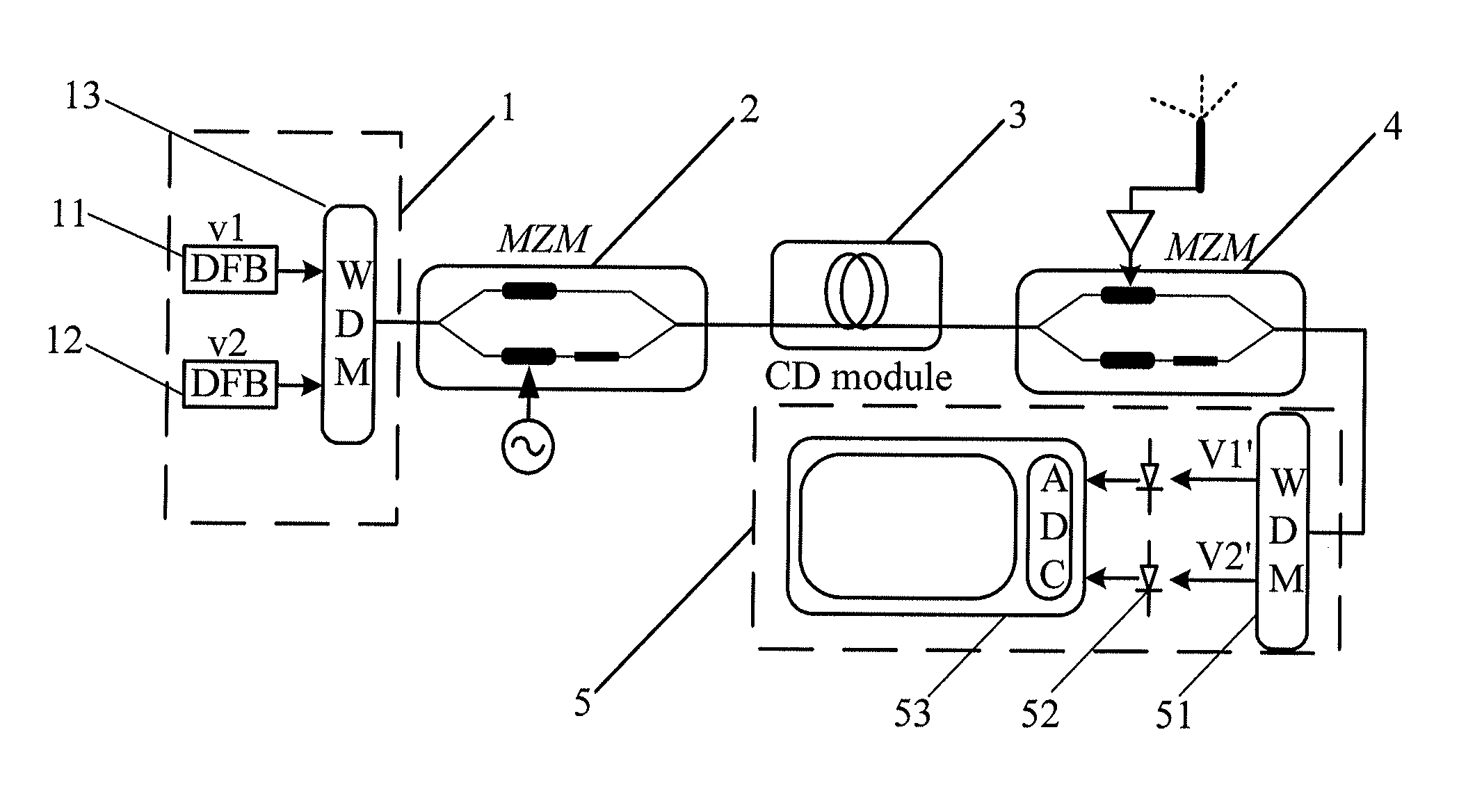
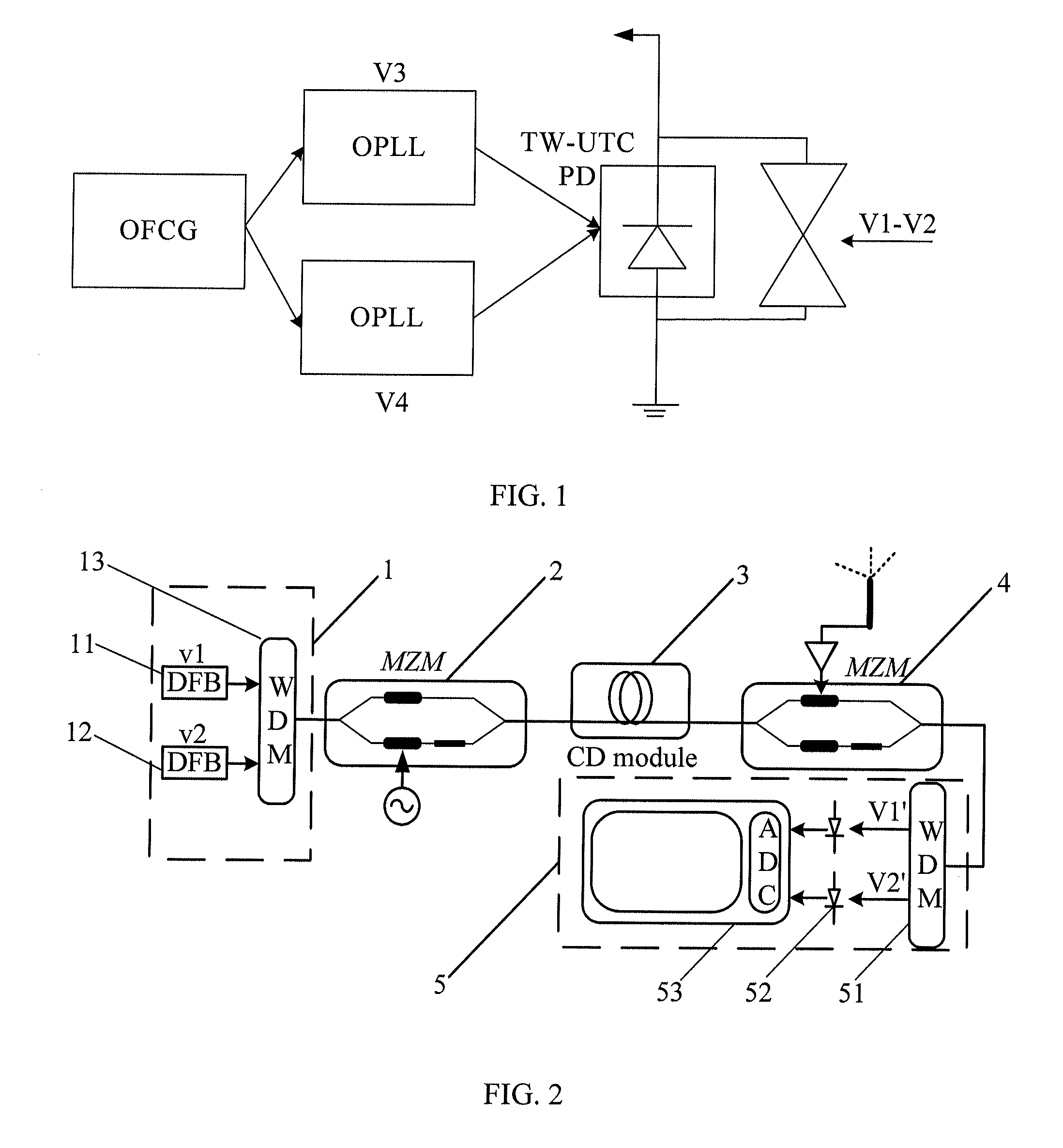
[0037]This embodiment provides a signal receiving device based on microwave photonics technologies. As shown in FIG. 2, the device includes:[0038]a signal generation module 1, a first Mach-Zehnder modulator 2, a dispersion module 3, a second Mach-Zehnder modulator 4, and a signal conversion module 5.

[0039]The working principle of the Mach-Zehnder modulator (Mach-Zehnder Modulator, abbreviated as MZM) is to split input light into two equivalent signals, which respectively enter two optical branches of the modulator. The two optical branches are made from an electrical-to-optical material whose refractive index varies with the level of an external electrical signal applied. As the variation of the refractive index of the optical branches can cause the change of the phase of a signal, when the signals in the two branches are combined again at an output end of the modulator, the combined optical signal is an interference signal with changed intensity, thereby achieving the modulation of...

embodiment 2

[0045]This embodiment provides a signal receiving method based on microwave photonics technologies. As shown in FIG. 8, the method includes:

[0046]Step 201: Generate a beam of signals including two optical signals with different wavelengths.

[0047]For example, the beam of signals including the two optical signals with different wavelengths may be generated by a signal generation module. Furthermore, the signal generation module includes two lasers and one wavelength division multiplexer, the two lasers are configured to obtain the two optical signals with different wavelengths, and the wavelength division multiplexer is configured to combine the two optical signals with different wavelengths into the beam of optical signals.

[0048]Step 202: Modulate the signals including the two optical signals with different wavelengths into a first signal, in which the first signal includes two signals each carrying a receiving microwave carrier frequency.

[0049]For examples, in this embodiment, a fir...

embodiment 3

[0061]This embodiment provides a signal receiving device based on microwave photonics technologies. As shown in FIG. 2, the device includes:[0062]a signal generation module 1, a first Mach-Zehnder modulator 2, a dispersion module 3, a second Mach-Zehnder modulator 4, and a signal conversion module 5.

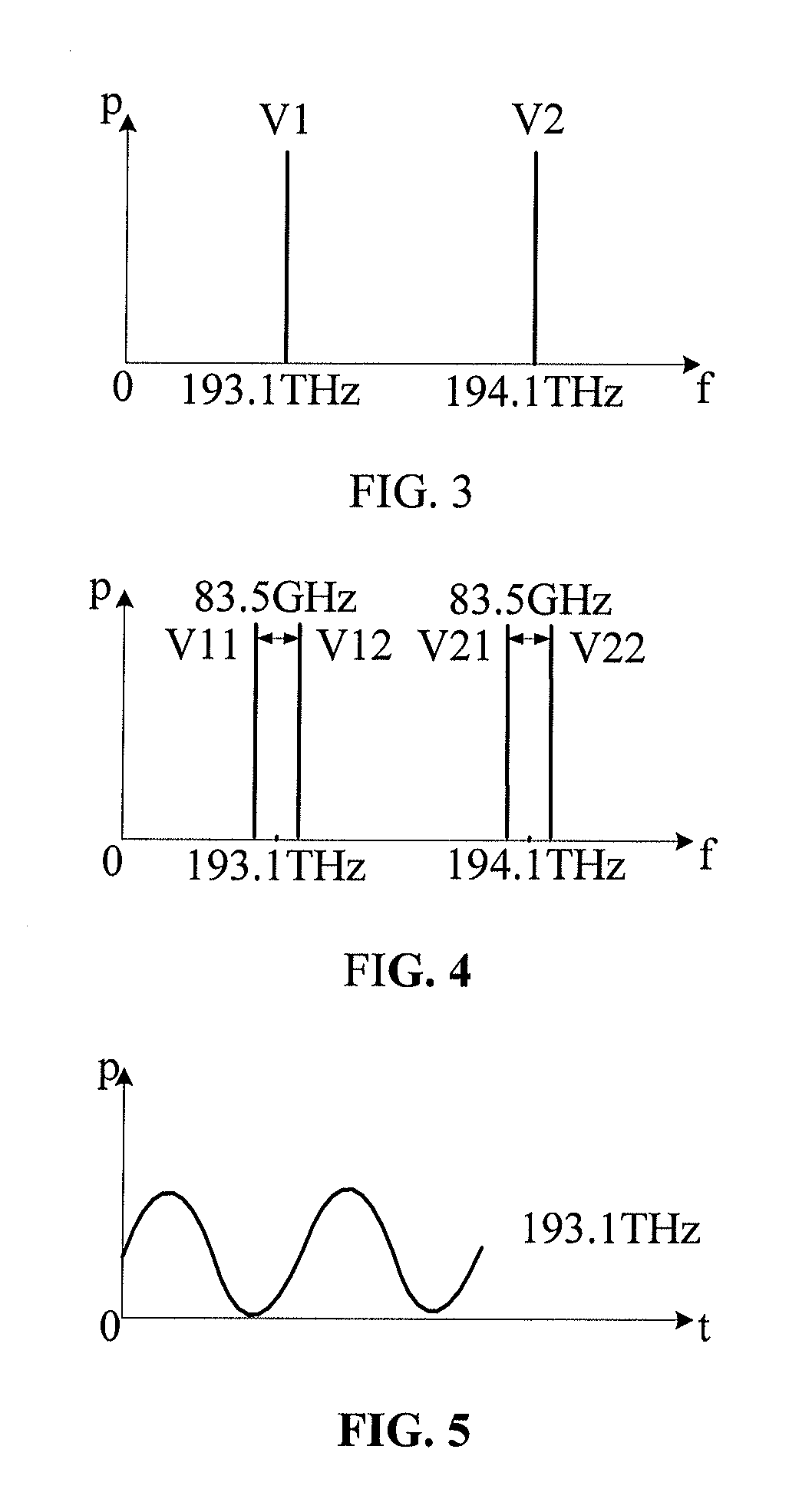
[0063]In this embodiment, the signal generation module 1 includes a first laser 11, a second laser 12, and a first wavelength division multiplexer 13. As shown in FIG. 3, the first laser 11 and the second laser 12 are configured to obtain two optical signals with different wavelengths, in which frequencies of the two optical signals are V1 and V2 respectively, and the frequency V1 is 193.1 THz and the frequency V2 is 194.1 THz. The first wavelength division multiplexer 13 is configured to combine the two optical signals with different wavelengths into a beam of optical signal, where the frequencies of the two optical signals are V1 and V2, respectively. The signal generation module 1 is ...


PUM


Abstract

A microwave photonics based signal receiving device includes a signal generation module, a first Mach-Zehnder modulator, a dispersion module, a second Mach-Zehnder modulator, and a signal conversion module. The signal receiving device simplifies a structure of the signal receiving device by adopting quadrature demodulation. The signal receiving device demodulates a high-order modulation signal and flexibly adjusts a microwave carrier frequency.

Description

CROSS-REFERENCE TO RELATED APPLICATIONS[0001]This application is a continuation of International Application No. PCT / CN2011 / 073071, filed on Apr. 20, 2011, which is hereby incorporated by reference in their entiretiesFIELD OF THE APPLICATION[0002]The present application relates to the field of communications, and in particular, to a signal receiving device and a signal receiving method based on microwave photonics technologies.BACKGROUND OF THE APPLICATION[0003]With the arising and application of 3G and 4G technologies, wireless communications impose an increasingly high requirement on the transmission rate, and microwave photonics technologies have gradually become an important technology in wireless communications due to the advantage of high speed.[0004]A wireless communication system generally includes a signal transmitter and a signal receiving device. In the prior art, a signal receiving device based on microwave photonics technologies is provided. As shown in FIG. 1, the sign...

Claims


Application Information

Patent Timeline
Patent Type & Authority Applications(United States)
IPC IPC(8): H04B10/60H04B10/2575H04B10/90
CPCH04B1/28H04B10/60H04B10/90H04B10/2575
Inventor WAN, WENTONGLI, KUNDONG, LIMINYANG, YANFULV, CHAO
Owner HUAWEI TECH CO LTD
Why Eureka
Try Eureka