
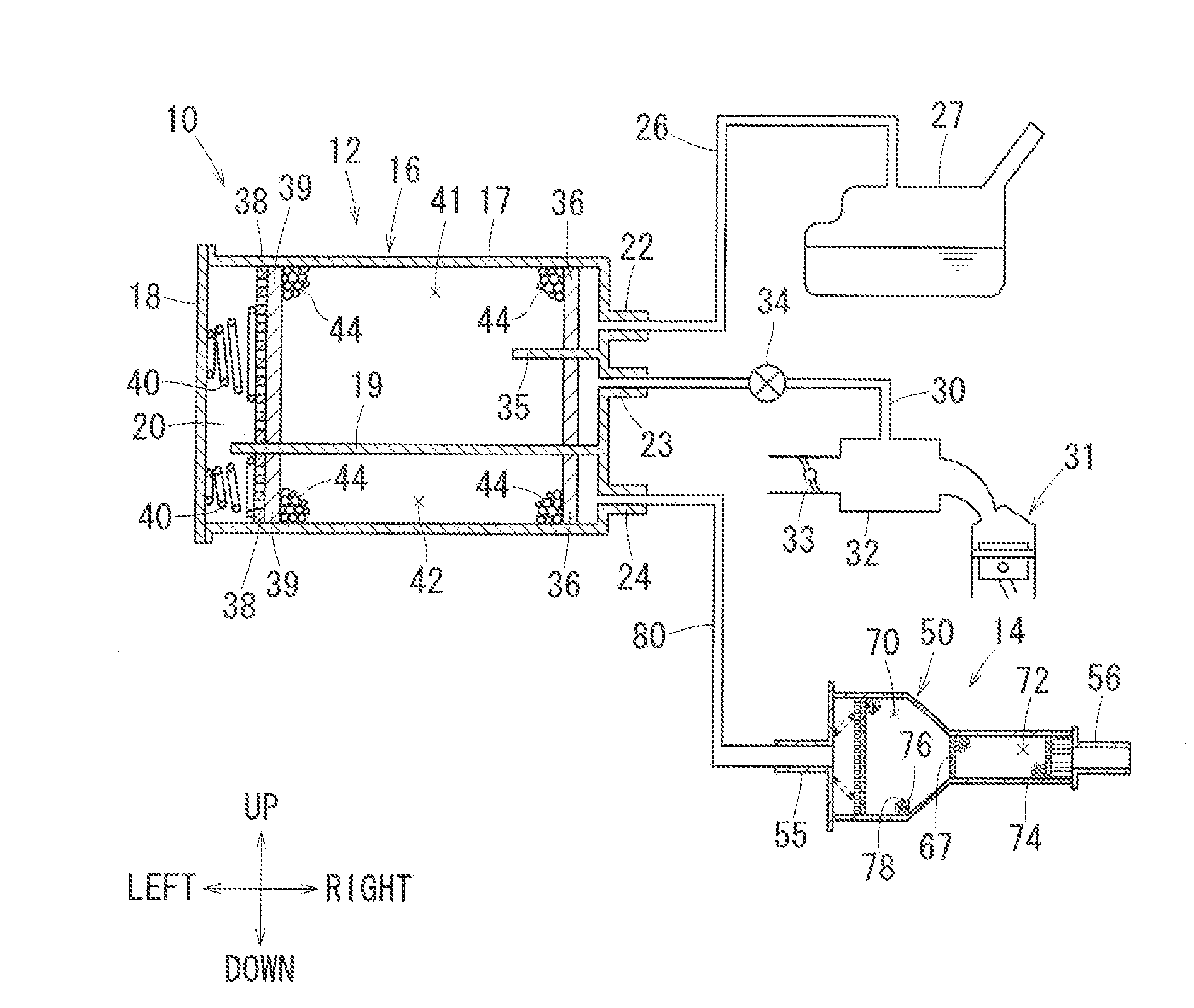
Trap canister capturing fuel vapor

a technology of fuel vapor and canister, which is applied in the field of canister, can solve the problems of difficult reduction of the amount of fuel vapor flowing into the atmosphere, difficult desorption of fuel vapor during purging operation, etc., and achieve the effects of reducing the amount of fuel vapor remaining, preventing increase in pressure loss, and small cross-sectional area

Inactive Publication Date: 2013-07-25
AISAN IND CO LTD
View PDF8 Cites 33 Cited by
  • Summary
  • Abstract
  • Description
  • Claims
  • Application Information

AI Technical Summary

Benefits of technology

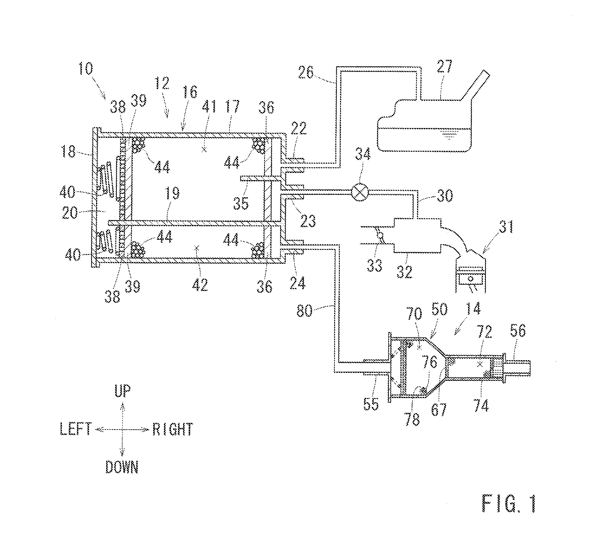
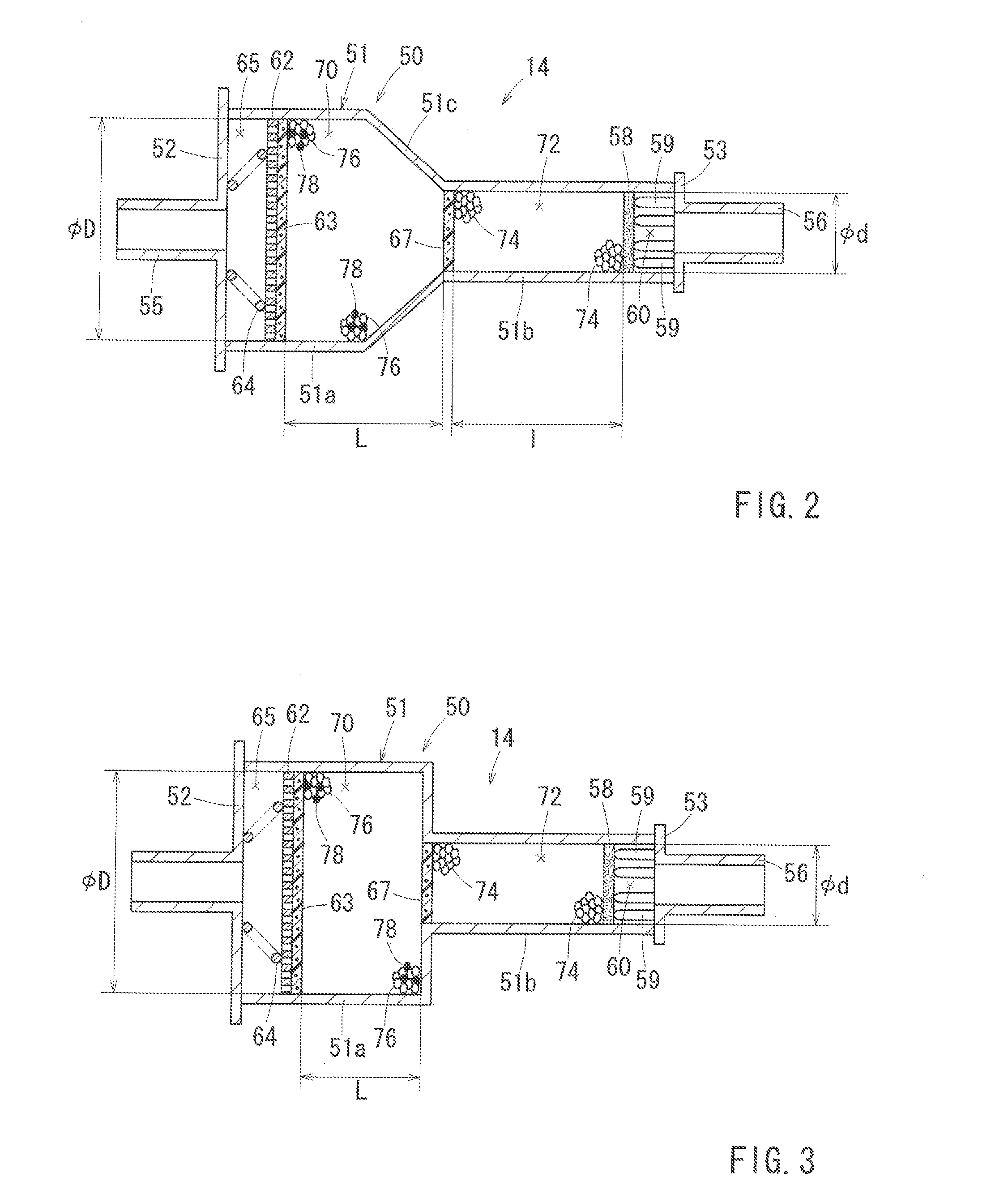
This patent describes a system for reducing fuel vapor and pressure loss in a vehicle's evaporative emission control system. The system includes two chambers, with the first chamber having a larger cross-sectional area than the second chamber. This allows the first chamber to absorb any increase in pressure loss caused by the second chamber, reducing the amount of fuel vapor remaining in the system. The first chamber also contains a latent heat storage material, which helps prevent temperature alteration of the adsorbent and further reduces the amount of fuel vapor remaining in the system. The second chamber is designed with a smaller cross-sectional area, allowing it to completely desorb fuel vapor from the adsorbent during purging operations. This system helps achieve a decrease in fuel vapor passing through the system and maintains stable adsorption and desorption ability.

Problems solved by technology

Thus, when fuel vapor is captured in the pore with the smaller opening, the fuel vapor is hard to desorb during the purging operation.
Thus, it has been difficult to decrease the amount of the fuel vapor flowing into the atmosphere from the trap canister while decreasing pressure loss.

Method used


Image

  • Trap canister capturing fuel vapor
  • Trap canister capturing fuel vapor
  • Trap canister capturing fuel vapor

Examples


Embodiment Construction

[0010]Each of the additional features and teachings disclosed above and below may be utilized separately or in conjunction with other features and teachings to provide improved trap canisters. Representative examples of the present invention, which examples utilized many of these additional features and teachings both separately and in conjunction with one another, will now be described in detail with reference to the attached drawings. This detailed description is merely intended to teach a person of skilled in the art further details for practicing preferred aspects of the present teachings and is not intended to limit the scope of the invention. Only the claims define the scope of the claimed invention. Therefore, combinations of features and steps disclosed in the following detailed description may not be necessary to practice the invention in the broadest sense, and are instead taught merely to particularly describe representative examples of the invention. Moreover, various fe...


PUM


Abstract

A trap canister is configured to capture fuel vapor contained in breakthrough gas discharged from an adsorbent canister. The trap canister has a housing defining an adsorption chamber therein, a breathable partition member disposed in the housing and dividing the adsorption chamber into a first chamber and a second chamber, an adsorbent filled in the first chamber and the second chamber, and a latent heal storage material tilled in the first chamber in a mixed manner with the adsorbent. The first chamber is configured to receive breakthrough gas, while the second chamber is configured to communicate with the atmosphere. The first chamber has a cross-sectional area larger than that of the second chamber.

Description

[0001]This application claims priority to Japanese patent application serial number 2012-12001, the contents of which are incorporated herein by reference.BACKGROUND OF THE INVENTION[0002]This invention relates to a trap canister that is mainly used for vehicle, in particular to a trap canister configured to adsorb fuel vapor contained in breakthrough gas discharged from an adsorbent canister.[0003]A conventional trap canister has a housing having one end communicating with the atmosphere and the other end receiving breakthrough gas from an adsorbent canister. The housing defines therein an adsorption chamber filled with activated carbon, i.e., adsorbent capable of adsorbing and desorbing fuel vapor. Japanese Laid-Open Patent Publication No. 2005-35812 discloses a trap canister defining therein an adsorption chamber having the same cross-sectional area over a path length along a flow direction of breakthrough gas.[0004]When the adsorbent canister (referred to as “main canister”, her...

Claims


Application Information

Patent Timeline
Patent Type & Authority Applications(United States)
IPC IPC(8): F02M25/06
CPCF02M25/0854F02M25/06
Inventor HASEGAWA, MASAKAZUKOSUGI, RYUJI
Owner AISAN IND CO LTD
Learn More