
Programmable power tool with brushless DC motor

a programmable power tool and brushless dc motor technology, applied in the direction of motor/generator/converter stopper, electronic commutator, dynamo-electric converter control, etc., can solve the problems of reducing the speed of the brushless dc motor, affecting the performance of the power tool, and rotor spinning, etc., to improve the tool path/location, improve the performance characteristics of the power tool, and improve the effect of precision stopping, revers

Active Publication Date: 2013-07-25
TRANSFORM SR BRANDS LLC
View PDF50 Cites 104 Cited by
  • Summary
  • Abstract
  • Description
  • Claims
  • Application Information

AI Technical Summary

Benefits of technology

This patent describes a power tool that uses brushless DC motor technology to improve its performance. The tool can be programmed to monitor, display, and control the motor's torque or speed, as well as provide precise stopping, reversing, or partial revolutions of the motor. Additionally, the tool may have safety features and a strobe lighting effect to make it easier to see the tool's path.

Problems solved by technology

During operation of the motor, the flow of electricity through the windings may generate a magnetic flux that results in the spinning of the rotor.
However, other applications of the tool may require precise control and operation of the motor.
However, typically, the speed of the brushless DC motor may decrease as load is applied to the tool.
Similarly, an increase in the torque demands on the motor may result in a decrease in the speed of the motor.
Such changes in motor speed, however, may result in variances in the quality of the polishing provided by the operation of the tool.
However, variability in the control and operation of the brushless DC motors may prohibit and / or limit the use of power tools powered by such motors in these torque specific applications.
The variability in the control and operation of the DC motor of power tools may also preclude precise control of starting and stopping locations of the motor, and moreover, the associated positioning of the component that is being driven by the motor.
However, given the generally imprecise nature of the operation of brushless DC motor tools, the tap bit typically is not generally stopped at the desired revolution intervals.

Method used


Image

  • Programmable power tool with brushless DC motor
  • Programmable power tool with brushless DC motor
  • Programmable power tool with brushless DC motor

Examples


Embodiment Construction

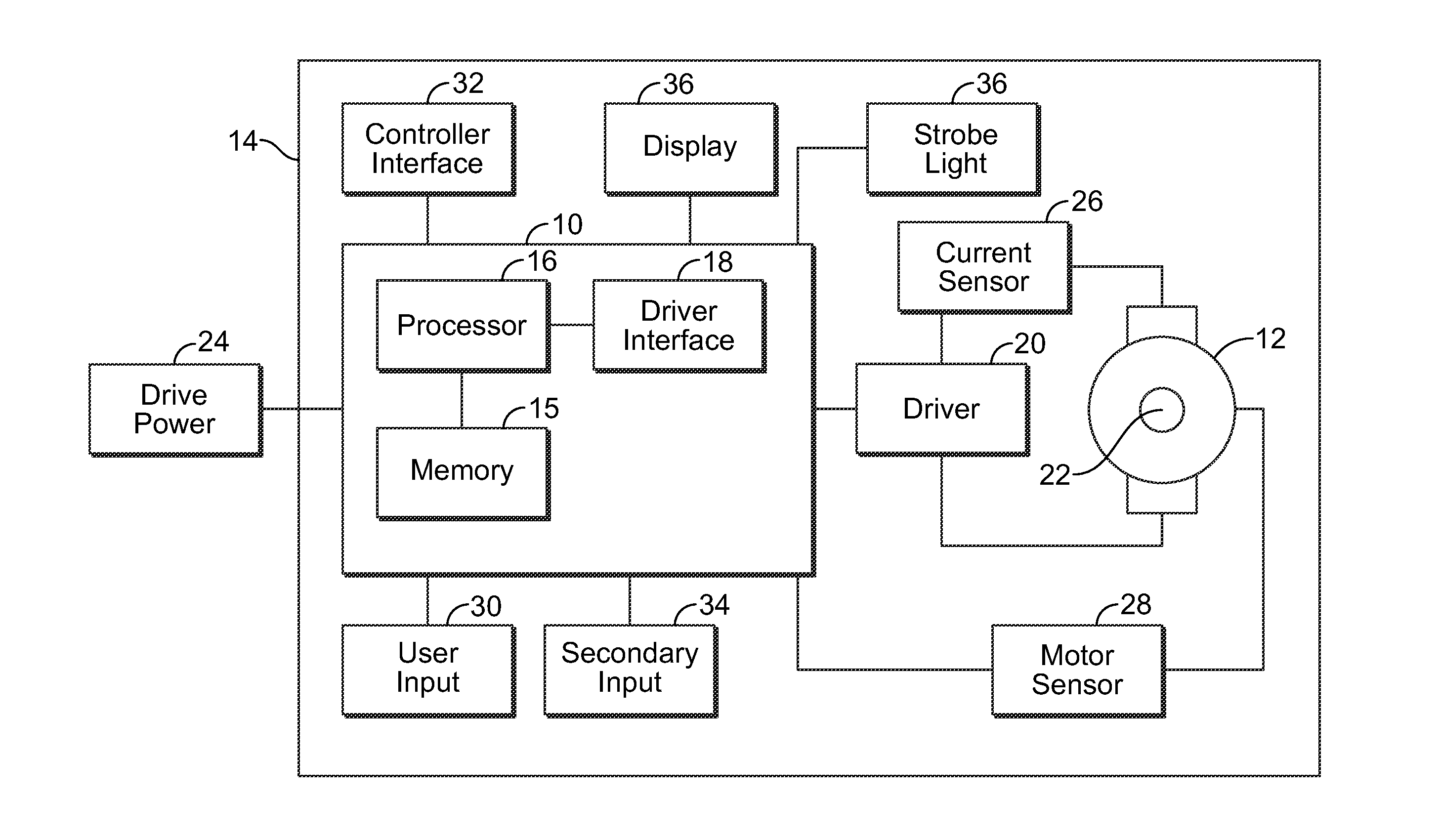
[0020]FIG. 1 illustrates a block diagram of a controller 10 and a brushless DC motor 12 for a power tool 14 according to certain embodiments of the present invention. A wide range of power tools 14 may be powered by the brushless DC motor 12, including, for example, tools that are typically, and generally, in a fixed location, such as, for example, lathes, table saws, drill presses, and milling machines, among others, as well as portable tools, including, for example, drills, routers, and impact drivers, among others. Examples of brushless DC motors 12 include, but are not limited to, out-runner brushless motors. Additionally, the tool 14 may be constructed from a variety of different materials, including, for example, alloy materials. According to certain embodiments, the tool 14 may be manufactured utilizing a Thixomolded process. Additionally, according to certain embodiments, the tool 14 may be provided with a waterproof and / or water-resistant housing to a certain depth. Accordi...


PUM


Abstract

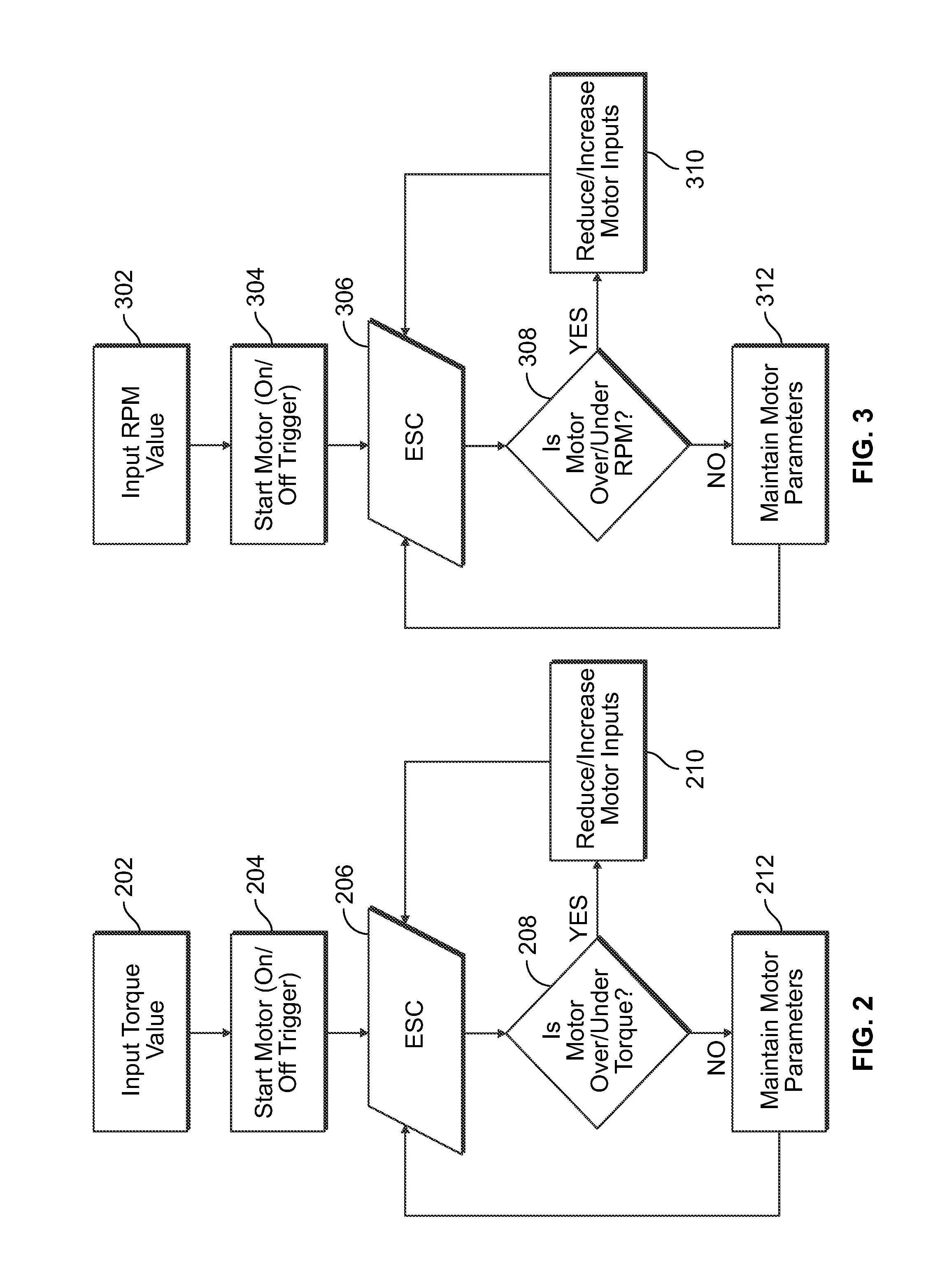
A power tool that includes a brushless DC motor, one or more motor sensors, and a controller, such as, for example, an electronic speed control (ESC) circuit. The controller is adapted to provide instructions to control the operation of one or more parameters of the brushless DC motor. The controller is also adapted to receive feedback from one or more motor sensors that reflect whether the motor is attaining the one or more parameters. The controller may also be adapted to have a learning mode, in which feedback provided during use of the power tool is stored by the controller as a program so that the same operating parameters may be subsequently replicated by using the program to operate the tool. The controller may also use the feedback to adjust the operation of the motor so that the motor maintains one or more selected or programed operating parameters.

Description

RELATED APPLICATIONS[0001]This application claims priority to U.S. Patent Application No. 61 / 583,846, having a filing date of Jan. 6, 2012, which is incorporated herein by reference in its entirety.BACKGROUND OF THE INVENTION[0002]The present application relates generally to power tools, and more particularly, to programmable power tools with a brushless DC motor.[0003]In certain applications, power tools may be powered by brushless DC motor technology, such as, for example, a brushless outrunner motor. Typically, a brushless outrunner motor includes stationary (stator) windings that are excited by conventional DC brushless controllers. During operation, a direct current, which is switched on and off at high frequency for voltage modulation, is typically passed through three or more non-adjacent windings together, and the group so energized is alternated electronically based upon rotor position feedback. The motor also includes permanent magnets that may be mounted on a rotor. Durin...

Claims


Application Information

Patent Timeline
IPC IPC(8): H02P6/16
CPCH02P6/08H02P6/16
Inventor KNIGHT, COLIN G.CORIC, MILOS
Owner TRANSFORM SR BRANDS LLC
Learn More