
Tunable broadband antenna matching circuits and devices using same

a broadband antenna and matching circuit technology, applied in the field of wireless transmitters and receivers, can solve the problems of limiting the throughput of data or information carried on the physical layer of wireless networks, preventing the efficient transfer of radio-frequency (rf) power, and further reducing the operating bandwidth below the antenna alone. , to achieve the effect of improving the wireless radio-frequency (rf) transmission system and reducing the imaginary part of the complex impedan

Inactive Publication Date: 2013-07-25
SAMSUNG ELECTRONICS CO LTD
View PDF5 Cites 9 Cited by
  • Summary
  • Abstract
  • Description
  • Claims
  • Application Information

AI Technical Summary

Benefits of technology

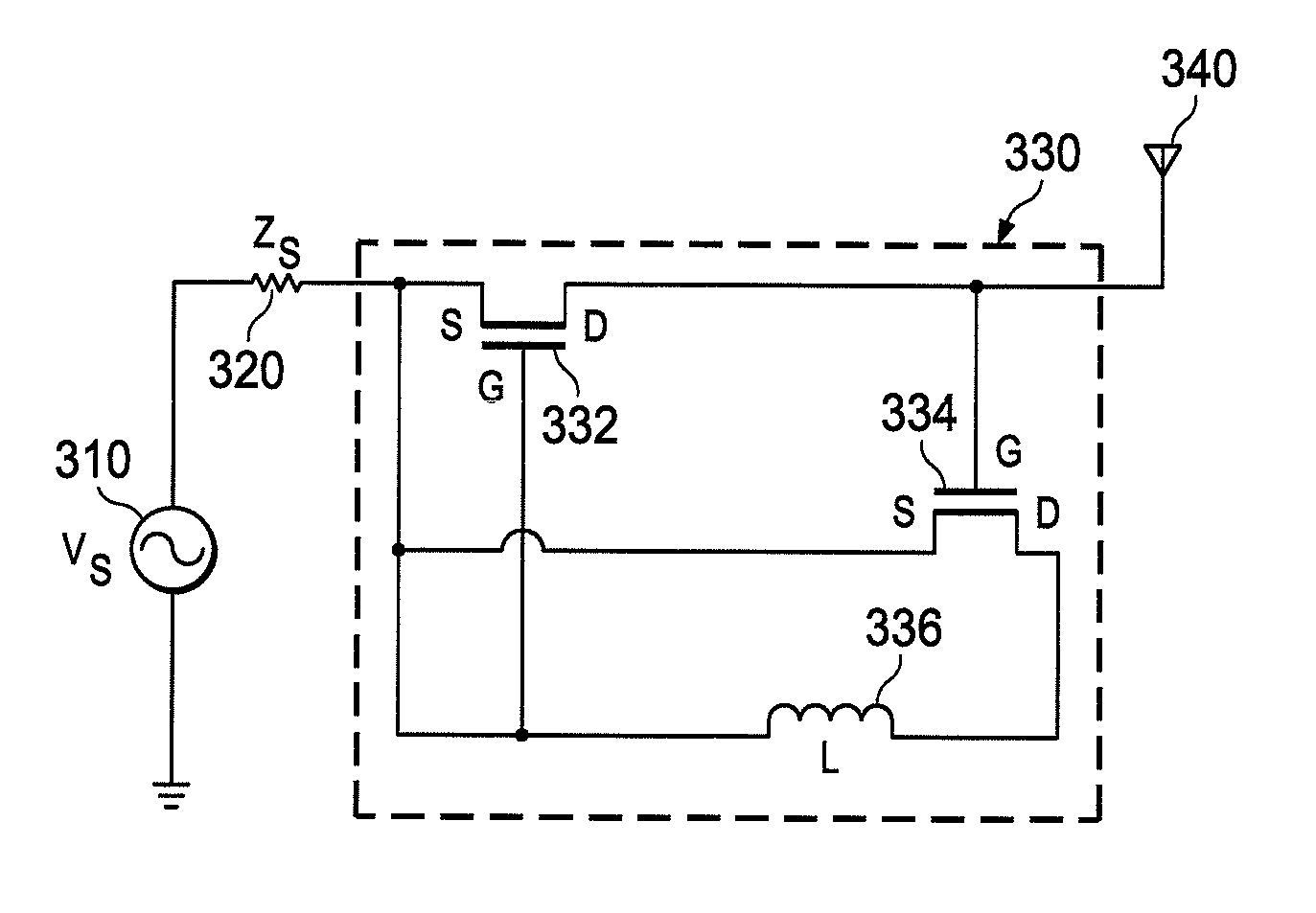
The invention is an improved wireless radio-frequency transmission system that includes a small antenna and a tunable negative impedance converter (NIC) circuit. The NIC circuit matches the antenna's complex impedance by reducing the imaginary part. The tuning of the NIC circuit can be done by adjusting a transconductance value or a tunable element within the circuit. The technical effect of this invention is improved wireless RF transmission with better coupling and more stable operation.

Problems solved by technology

These complicated impedances prevent the efficient transfer of radio-frequency (RF) power to and from the antenna feed-points and the radiating electromagnetic fields and limit the throughput of data or information carried on the physical layer of wireless networks.
Passive matching networks utilize fully passive components (inductors, capacitors, transformers, transmission lines, etc.) to achieve the impedance transformation but are limited to one or a few specific frequencies and may further reduce the operating bandwidth below that of the antenna alone.
Negative impedance circuit matching provides broadband matching at a single center frequency or within a single frequency band but cannot provide effective matching across multiple frequency bands.
Present antenna matching technologies do not provide adequate or effective means to address both the bandwidth and frequency agility demanded of new wireless systems.

Method used


Image

  • Tunable broadband antenna matching circuits and devices using same
  • Tunable broadband antenna matching circuits and devices using same
  • Tunable broadband antenna matching circuits and devices using same

Examples


Embodiment Construction

[0016]FIGS. 1 through 5, discussed below, and the various embodiments used to describe the principles of the present disclosure in this patent document are by way of illustration only and should not be construed in any way to limit the scope of the disclosure. Those skilled in the art will understand that the principles of the present disclosure may be implemented in any suitably arranged radio frequency (RF) transmitter and / or receiver.

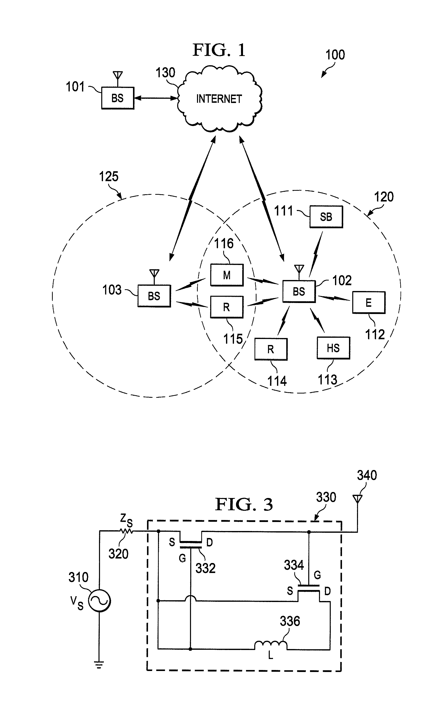
[0017]FIG. 1 illustrates exemplary wireless network 100, which includes mobile stations that implement tunable broadband antenna matching according to the principles of the present disclosure. Wireless network 100 includes base station (BS) 101, base station (BS) 102, base station (BS) 103, and other similar base stations (not shown). Base station 101 is in communication with Internet 130 or a similar IP-based network (not shown).

[0018]Depending on the network type, other well-known terms may be used instead of “base station,” such as “eNodeB” or “ac...


PUM


Abstract

An improved wireless radio-frequency (RF) transmission system is disclosed. The wireless RF transmission system comprises: 1) a radio frequency (RF) transceiver configured to transmit and receive radio-frequency signals; ii) an electrically small antenna having a complex impedance comprising a real part and an imaginary part; and iii) a tunable negative impedance converter (NIC) circuit coupling the electrically small antenna to the RF transceiver. The tunable NIC circuit is configured to perform antenna matching by reducing the imaginary part of the complex impedance of the electrically small antenna. The tunable NIC circuit is tuned by adjusting a transconductance value associated with the tunable NIC circuit.

Description

TECHNICAL FIELD OF THE INVENTION[0001]The present application relates generally to wireless transmitters and recievers and, more specifically, to a tunable broadband antenna matching circuit for use with an electrically small antenna having physical dimensions less than the operating wavelength of the wireless device.BACKGROUND OF THE INVENTION[0002]An antenna with physical dimensions less than the operating wavelength of the antenna, frequently called and “electrically small antenna” or “ESA”, exhibits complicated electrical impedances at the antenna feed-points. These complicated impedances prevent the efficient transfer of radio-frequency (RF) power to and from the antenna feed-points and the radiating electromagnetic fields and limit the throughput of data or information carried on the physical layer of wireless networks.[0003]The following reference (REF) documents are incorporated by reference into the present disclosure as if fully set forth herein: i) REF1—M. Gustafsson, C. ...

Claims


Application Information

Patent Timeline
IPC IPC(8): H01Q1/50
CPCH03H11/30H01Q1/243
Inventor HUTCHESON, GEORGE ZOHN
Owner SAMSUNG ELECTRONICS CO LTD
Learn More