
Device and method for the recovery of waste heat of an internal combustion engine

a technology of waste heat recovery and internal combustion engine, which is applied in the direction of machines/engines, lighting and heating apparatus, and greenhouse gas reduction. it can solve the problems of loss of heat energy given off by the exhaust gas system, and achieve the effect of reducing pressure fluctuations in the heat exchanger and the connecting lin

Inactive Publication Date: 2013-08-01
ROBERT BOSCH GMBH
View PDF26 Cites 9 Cited by
  • Summary
  • Abstract
  • Description
  • Claims
  • Application Information

AI Technical Summary

Benefits of technology

The invention provides a system for storing and using heat energy in an efficient manner in an expansion engine. A steam accumulator is placed between the heat exchanger and the engine to minimize heat loss and make the energy available when needed. The system also allows for control of the thermodynamic circuit through which the working medium flows. Overall, the system optimizes energy utilization and reduces pressure fluctuations.

Problems solved by technology

The heat energy given off by the exhaust gas system would be lost if a suitable storage system were not available.

Method used


Image

  • Device and method for the recovery of waste heat of an internal combustion engine
  • Device and method for the recovery of waste heat of an internal combustion engine
  • Device and method for the recovery of waste heat of an internal combustion engine

Examples


Embodiment Construction

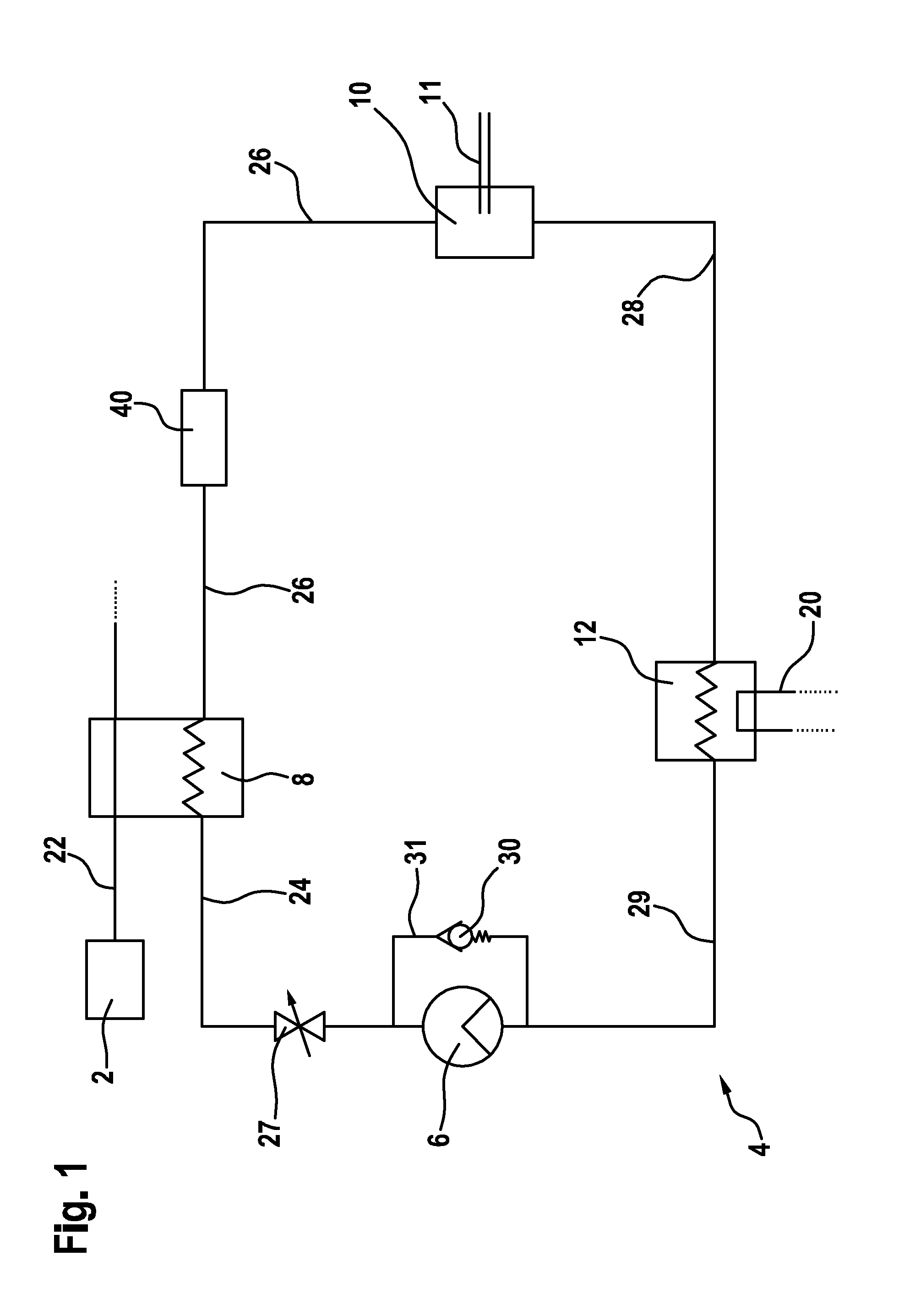
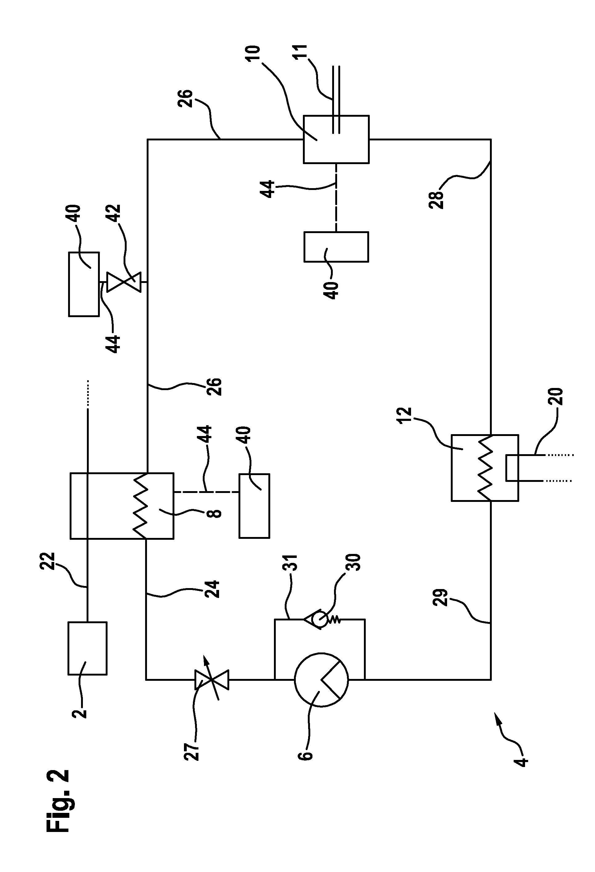
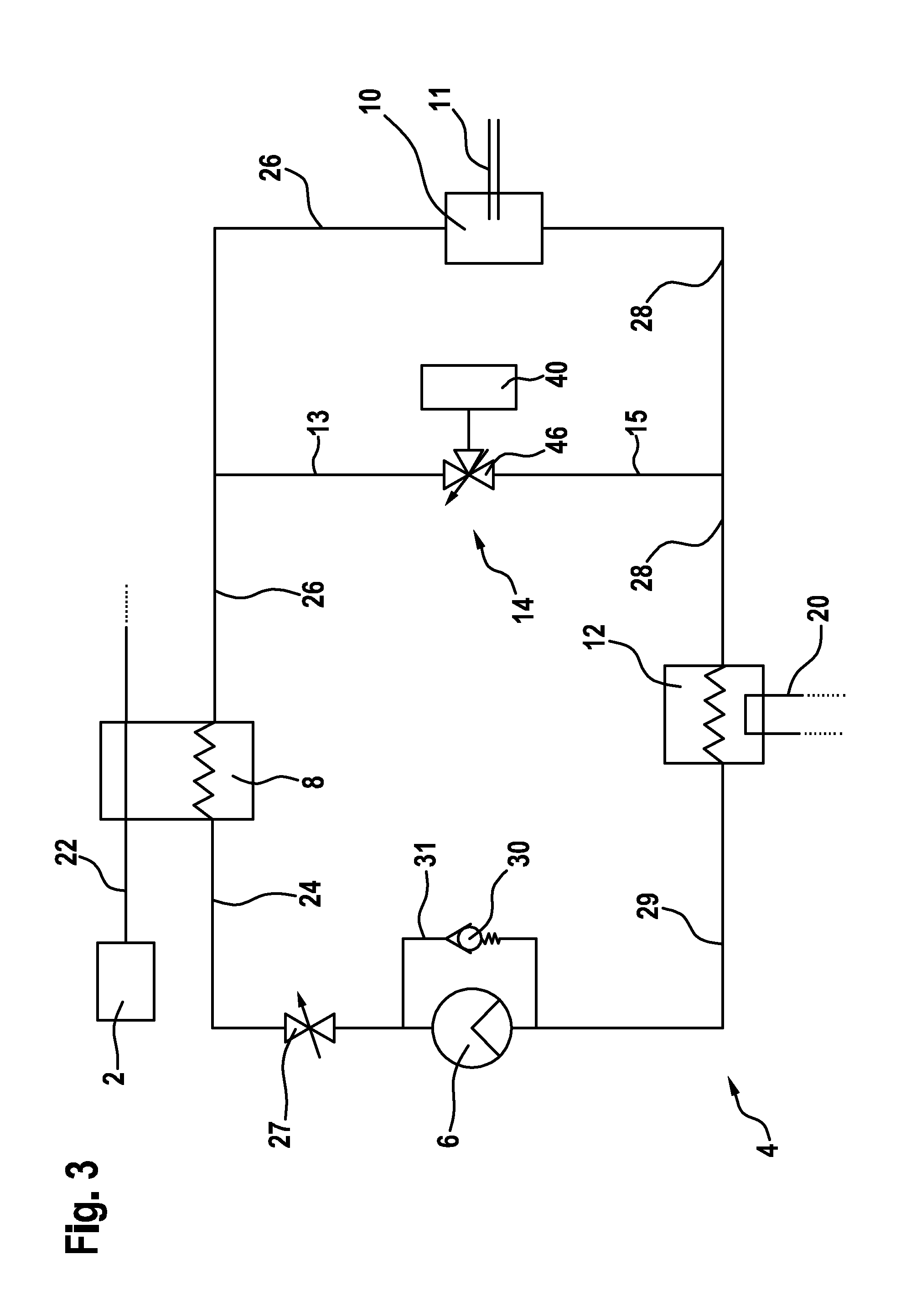
[0021]FIGS. 1 to 4 show a device for the recovery of waste heat from an internal combustion engine 2 comprising a circuit 4 containing a circulating working medium. At least one heat exchanger 8, an expansion engine 10, a condenser 12 and a feed pump 6 are disposed in the circuit 4. A steam accumulator 40 for storing a vaporous working medium is furthermore provided in the circuit 4, as is later described in detail in the description of the individual exemplary embodiments.

[0022]The internal combustion engine 2 can particularly be embodied as an air-compressed, self-ignited internal combustion engine 2 or as a mixture-compressed, spark-ignited internal combustion engine 2. The device for waste heat recovery is specially suited to applications in motor vehicles. Said inventive device for waste heat recovery is, however, also suited to other applications.

[0023]The internal combustion engine 2 burns fuel in order to produce mechanical energy. The exhaust gases resulting in the process ...


PUM


Abstract

The invention relates to a device and a method for the recovery of waste heat from an internal combustion engine (2). A feed pump (6), a heat exchanger (8), an expansion engine (10) and a capacitor (12) are arranged in a circuit (4) containing a circulating working medium. A steam accumulator (40) for storing the vaporous working medium is also arranged in the circuit (4).

Description

BACKGROUND OF THE INVENTION[0001]The German patent publication DE 10 2006 057 247 A1 discloses a charging unit, which serves to recover waste heat from an internal combustion engine. At least one heat exchanger of a circuit of a working medium is housed in the exhaust system of the internal combustion engine. In addition, a turbine part and a conveyor assembly are disposed in the circuit. A compressor part disposed in the intake system of the internal combustion engine is driven via the turbine part.SUMMARY OF THE INVENTION[0002]The device according to the invention for the recovery of waste heat of an internal combustion engine and the associated inventive method having the features of the independent claims have the advantage that steam, which is not required at a certain point in time, is stored and is passed on only when required or when a load demand is placed on the expansion engine.[0003]When a momentary change in load on the internal combustion engine occurs, as is the case ...

Claims


Application Information

Patent Timeline
Patent Type & Authority Applications(United States)
IPC IPC(8): F01K23/06
CPCF01K3/08F22B1/1807F01K25/08F01K23/065Y02E20/30
Inventor REWERS, GREGORYEISENMENGER, NADJABRENK, ACHIMSEHER, DIETERMAGEL, HANS-CHRISTOPHWENGERT, ANDREAS
Owner ROBERT BOSCH GMBH
Learn More