Coupling Unit and Battery Module having an Integrated Pulse-Controlled Inverter and Increased Reliability

a technology of pulse-controlled inverters and coupling units, which is applied in the direction of battery arrangements, electrical devices, safety/protection circuits, etc., can solve the problems of high capacitance, high cost and space requirements, and considerable potential for servicing personnel or the like being injured, so as to increase the service life of the battery. , the effect of reducing the exten

Inactive Publication Date: 2013-08-01
SAMSUNG SDI CO LTD +1
View PDF9 Cites 13 Cited by
  • Summary
  • Abstract
  • Description
  • Claims
  • Application Information

AI Technical Summary

Benefits of technology

[0013]The control unit can also be designed to connect all the first inputs of the coupling units of a selected battery module line to the outputs of the coupling units of the selected battery module line at a first time and all the second inputs of the coupling units of the selected battery module line to the outputs of the coupling units of the selected battery module line at a second time. As a result, the full output voltage of the selected battery module line is provided at the output of the battery module line at the first time, while a voltage of 0 V is output at the second time. As a result, the coupling units of the battery module line are operated as a pulse-controlled inverter which, as shown in FIG. 1, connects either the positive pole or the negative pole of the DC voltage intermediate circuit to the outputs of the pulse-controlled inverter. By virtue of using, for example, a pulse-width-modulated actuation means, an approximately sinusoidal output voltage can be generated in this way, with the motor windings of the drive motor acting as filters. The battery of the invention can therefore completely take on the function of the pulse-controlled inverter of the prior art. In an embodiment with a plurality of battery module lines, each battery module line can generate an output voltage, the phase of said output voltage being shifted in relation to the other battery module lines, so that a drive motor can be directly connected to the battery. In this case, it is additionally advantageous for the total capacitance of the battery to be distributed between a plurality of battery module lines, as a result of which parallel connection of battery cells can be dispensed with or can be performed at least to a considerably lower extent. As a result, compensation currents between battery cells which are connected in parallel are eliminated or at least reduced, this increasing the service life of the battery. Instead of a single DC voltage intermediate circuit as in FIG. 1, the number of DC voltage intermediate circuits provided is therefore equal to the number of battery module lines. This provides the advantage that any buffer capacitors which may be provided can be of smaller dimensions or can be completely dispensed with.

Problems solved by technology

However, one problem in this case is that compensation currents between the battery cells which are connected in parallel may occur on account of cell capacitances and voltages which are not exactly identical.
Owing to the usually very high voltage of the DC voltage intermediate circuit, a capacitance as high as this can be realized only with high costs and a high space requirement.
Otherwise, there is a considerable potential for servicing personnel or the like being injured on account of the high DC voltage of the series-connected battery cells.
In addition to the high total voltage, the connection of a large number of battery cells in series is associated with the problem of the entire battery failing when a single battery cell fails because the battery current has to be able to flow in all of the battery cells due to the series connection.
Failure of the battery in this way can lead to a failure of the entire system.
In an electric vehicle, a failure of the drive battery leads to a so-called breakdown; in other apparatuses, for example the rotor blade adjustment means in wind power installations in strong winds, situations which put safety at risk may even occur.

Method used


Image

  • Coupling Unit and Battery Module having an Integrated Pulse-Controlled Inverter and Increased Reliability
  • Coupling Unit and Battery Module having an Integrated Pulse-Controlled Inverter and Increased Reliability
  • Coupling Unit and Battery Module having an Integrated Pulse-Controlled Inverter and Increased Reliability

Examples


first embodiment

[0026]FIG. 4 shows the coupling unit which has a changeover switch 34, which can in principle connect only one of the two inputs 31, 32 to the output 33, while the respective other input 31, 32 is decoupled from the output 33. The changeover switch 34 can be realized as electromechanical switches in a particularly simple manner.

second embodiment

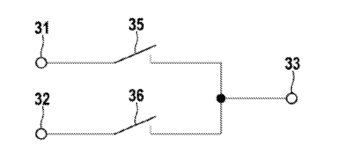
[0027]FIG. 5 shows the coupling unit in which a first and a second switch 35 and 36, respectively, are provided. Each of the switches is connected between one of the inputs 31 and 32, respectively, and the output 33. In contrast to the embodiment of FIG. 4, this embodiment provides the advantage that both inputs 31, 32 can also be decoupled from the output 33 so that the output 33 has a high impedance. In addition, the switches 35, 36 can be implemented in a simple manner as semiconductor switches, for example MOSFETs or IGBTs. Semiconductor switches have the advantage of a favorable price and a high switching speed, and therefore the coupling unit 30 can react to a control signal or a change in the control signal within a short time and high changeover rates can be achieved.

[0028]FIGS. 6A and 6B show two embodiments of the battery module 40 according to the invention. A plurality of battery cells 41 is connected in series between the inputs of a coupling unit 30. However, the inven...


PUM

PropertyMeasurementUnit
voltageaaaaaaaaaa
timeaaaaaaaaaa
voltageaaaaaaaaaa

Abstract

A coupling unit for a battery module, includes a first input, a second input and an output. The coupling unit is configured to connect the first input or the second input to the output in response to a control signal. The coupling unit and at least one battery cell are included in a battery module. The at least one battery cell is connected between the first input and the second input of the coupling unit. A first terminal of the battery module is connected to the output of the coupling unit, and a second terminal of the battery module is connected to the second input of the coupling unit.

Description

[0001]The present invention relates to a coupling unit for a battery module and a battery module having a coupling unit of this kind.PRIOR ART[0002]It has become apparent that, in the future, battery systems will be increasingly used, both in stationary applications and in vehicles such as hybrid and electric vehicles. In order to be able to meet the requirements in respect of voltage and available power given for a respective application, a large number of battery cells are connected in series. Since the current provided by a battery of this kind has to flow through all the battery cells and a battery cell can conduct only a limited current, additional battery cells are often connected in parallel in order to increase the maximum current. This can be done either by providing a plurality of cell windings within a battery cell housing or by externally interconnecting battery cells. However, one problem in this case is that compensation currents between the battery cells which are con...

Claims


Application Information

Patent Timeline
Patent Type & Authority Applications(United States)
IPC IPC(8): H02J1/00
CPCH02J7/0016H02J7/0026Y02T10/7055H02J1/00Y02T10/7011B60L11/1879Y02T10/7005Y02T10/705B60L11/1853B60L58/18B60L50/64Y02T10/70H02J7/0029H02J7/00
Inventor BUTZMANN, STEFANFINK, HOLGER
Owner SAMSUNG SDI CO LTD
Why Eureka
Try Eureka