Method and pneumatic material conveying system

a conveying system and pneumatic technology, applied in the field of pneumatic material conveying system, can solve the problems of high energy consumption, noise, high air flow in the piping, etc., and achieve the effect of effective rinse and drying, and reducing the diameter of the main conveying pip

Active Publication Date: 2013-08-01
MARICAP OY
View PDF13 Cites 5 Cited by
  • Summary
  • Abstract
  • Description
  • Claims
  • Application Information

AI Technical Summary

Benefits of technology

[0011]The solution according to the invention has a number of important advantages. By using the system in waste material conveying in two phases, of which in the first phase the input points are emptied and their waste material is transferred from a branch pipe into a main conveying pipe and in the second phase the wastes are transferred from the main conveying pipe into a separating means, in which case the main conveying pipe is used as an intermediate reservoir. In the solution according to the invention a pump unit can thus, in a way, be split into two such that two branch conveying pipes can be sucked at the same time. Suction occurs from the branch pipes, which are generally smaller in diameter than the main conveying pipe. The output of smaller pump units is sufficient to transfer waste at least up to the main conveying pipe. It is possible therefore to transfer with low power at least a part of the conveying distance from an input point to the main conveying pipe, which can be used as a reservoir. When a sufficient amount of waste has been transferred from the input points via the branch pipes into the main conveying pipe, the whole output of the pump devices can be connected, if necessary, to suck from a part of the main conveying piping, in which case up to twice the speed is obtained and the waste transfers to a waste station, into a separating means. Next the transfer can be connected to a second section of the main conveying pipe, in which case the main conveying piping empties. With this arrangement the output power of the fans can be up to halved. By connecting at least a part of the conveying piping to comprise a circuit, i.e. into a so-called ring-line piping, in the arrangement the piping can be effectively rinsed and dried. In this case also the blowing of a pump device is directed into the piping. By arranging in a first phase suction / partial vacuum in the main conveying pipe or in a section of the main conveying pipe from two different directions, at least in the proximity of the intersection of the branch conveying pipe intended to be emptied and the main conveying pipe, an effective transfer of waste material from a branch conveying pipe into the main conveying pipe is achieved. At the same time the pressure loss with respect to the main conveying pipe halves. Furthermore, the diameter of the main conveying pipe can be reduced. In the second phase conveying air can be circulated in the circuit formed partly by the conveying piping and an effective transfer of the waste material already transferred to the section of the main conveying pipe to a separating means of a waste station can be achieved. The direction of the conveying air circulation can be changed in the circuit, in which case the most suitable transport route, e.g. in terms of transport distance or energy use, can be optimized.
[0012]The invention enables the use of smaller pipe diameters of the conveying piping in pipe sections, which are connected at their second end to the conveying piping that forms a circuit but in which sections conveying air is not circulated, i.e. to a so-called “Single Line” section. According to one embodiment of the invention, the diameter of the main conveying pipe can also be reduced compared to conventional pipe transport systems. Considerable savings are gained by means of the embodiments, because the conveying piping is smaller in diameter and the conveying air volume needed for conveying material is smaller.
[0013]According to the invention a part of the piping can be connected into a circuit, in which case conveying air can be circulated e.g. for air-flushing of the piping or for removing humidity. An effective conveying effect can also be achieved in the different parts of the conveying piping and also a fast transfer from the input pipe into the conveying pipe. By arranging the piping of the system to comprise a circuit where at least a part of the conveying air circulates, the volume of outlet air can be decreased. At the same time the energy consumption of the system decreases. By maintaining a partial vacuum and at the same time maintaining blowing, an effective circulation of conveying air in the circuit and conveying of material in the conveying pipe can be achieved. With the solution according to the invention a conventional so-called “Single Line” system that comprises one conveying pipe can be efficiently combined with a solution in which at least a part of the conveying piping forms a circuit in which conveying air can be circulated, i.e. a Ring Line system. At the same time total energy consumption can be made more efficient when at least a part of the transport distance is performed in the conveying piping in which conveying air is circulated. This is a significant advantage, particularly in large waste-conveying systems that cover e.g. a whole city district or city.
[0014]When the Single Line and the Ring Line systems are connected, the Single Line pipe section can be selected to be smaller and the diameter of the Ring Line pipe section, i.e. the pipe section in which conveying air can be circulated in the circuit, to be larger, if necessary. In this case some of the air volume is sufficient to transfer wastes in the Single Line part of the piping into the Ring Line pipe section, i.e. into the pipe section that forms a circuit, in which conveying air can be circulated. The total power requirement decreases, in which case a considerable saving is achieved. Typically the saving is in the range of 30-50%. With the solution according to the invention, it is possible to essentially reduce the volume of outlet air and, at the same time, to reduce possible dust problems and fine particle problems in the outlet pipe. Furthermore, the odor nuisances of conveying pipings typical to conventional pneumatic conveying systems of wastes can be reduced. According to the invention at least a part of the conveying piping can be connected as a part of a circuit in which the suction effect to be achieved with the pump devices can be adjusted and / or controlled and / or opened or closed with closing means / adjustment means, such as with valve means, which are arranged in connection with the conveying piping. In this case suction can be efficiently circulated in the system even if the conveying piping of the system would not be a complete ring. At the same time efficient conveying of material can be achieved in the piping. With the method and apparatus according to the invention it is possible to efficiently adjust the relationship of the air to be blown into the conveying piping and the air to be blown out of the system. With the solution according to the invention, the noise problem caused by prior art can also be essentially reduced. Moisture accumulating in the piping decreases and the piping can be dried by circulating air in the piping. When the air to be sucked in decreases, the use of energy also decreases. By opening and closing the input points of the system according to the invention, efficient conveying of material into the conveying pipe and conveying in the conveying pipe are achieved, while at the same time it is possible to keep the noise impact caused by the operation of the system small. By arranging the conveying pipe of the material conveying system to be composed of operating areas, i.e. subcircuits, the conveying of material in the conveying piping and the emptying of input points into the conveying pipe can be effectively arranged. By arranging the conveying air circulation in the opposite direction an effective removal of clogging can be achieved. The change of the conveying air circulation into the other direction can be arranged easily in a ring piping. Also the total energy consumption decreases because, among other things, additional energy for drying the piping, heating the piping, etc., is not needed.

Problems solved by technology

In partial-vacuum conveying systems there are typically the following problems, among others: high energy consumption, high air flow in the piping, problems with noise, and dust and fine particle problems in the outlet pipe.
This results in very expensive solutions in terms of costs, and also as the pipe size increases more space is required for the installations.

Method used


Image

  • Method and pneumatic material conveying system
  • Method and pneumatic material conveying system
  • Method and pneumatic material conveying system

Examples


Embodiment Construction

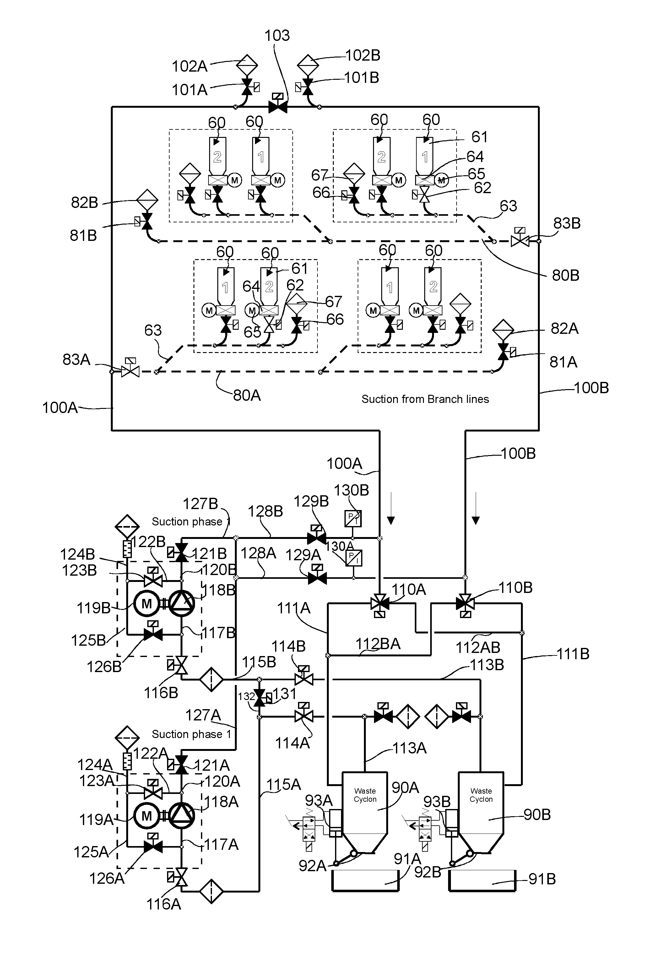
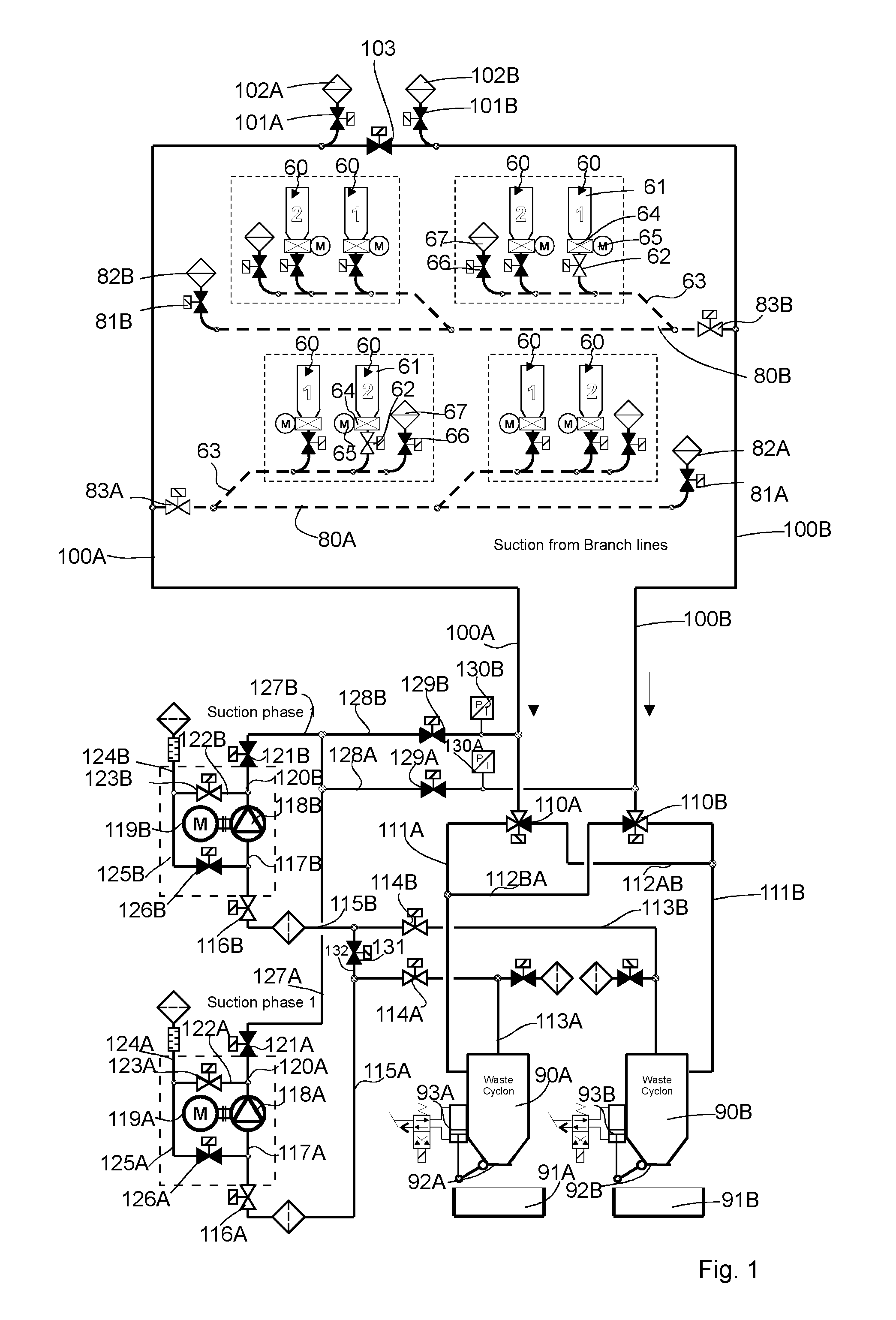
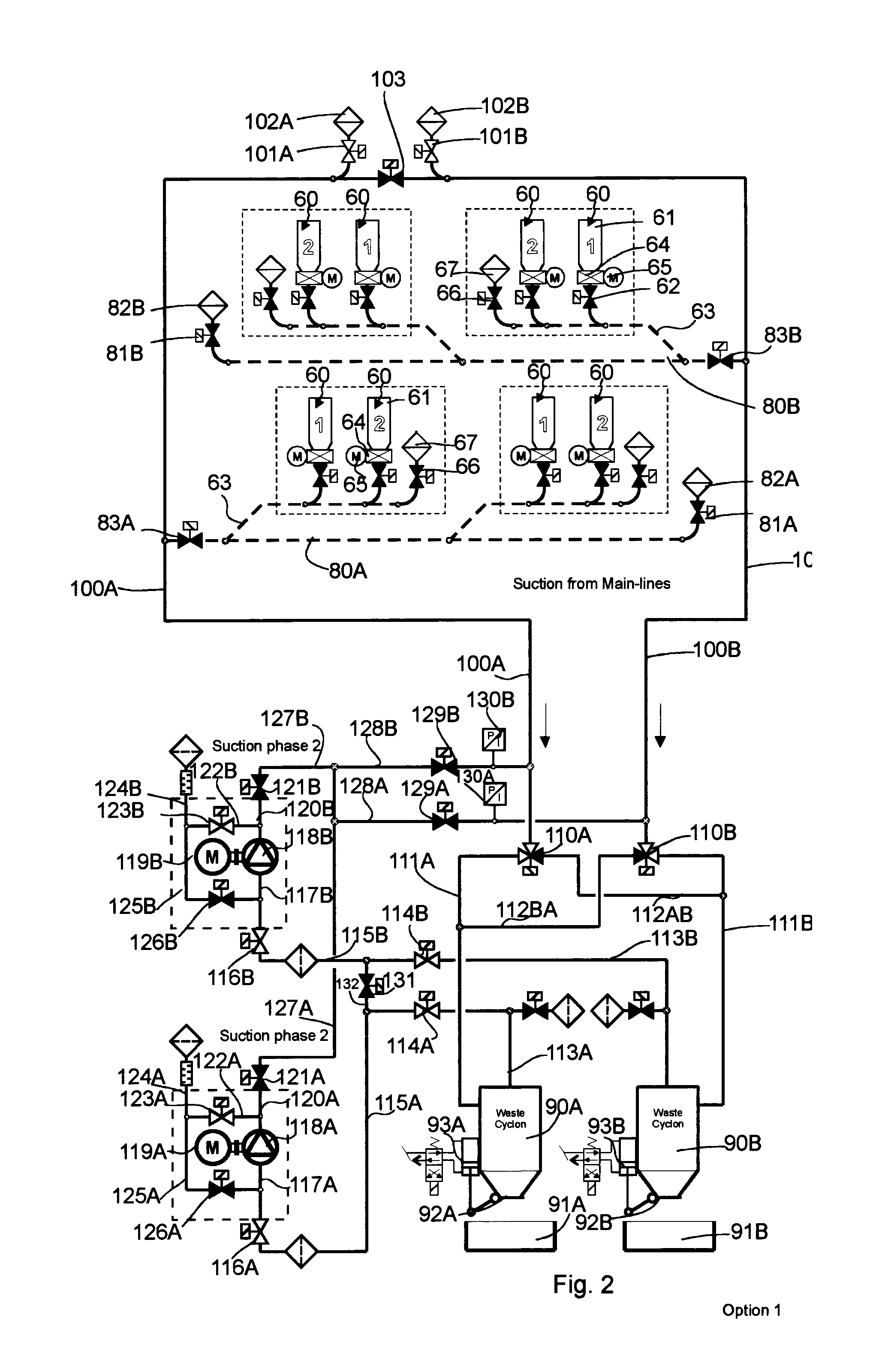
[0026]FIGS. 1-4 present a simplified diagram of a pneumatic material conveying system, more particularly a wastes conveying system, according to one embodiment according to the invention. The figure presents a main conveying pipe 100A, 100B for material, along the side of which main conveying pipe at least one, typically many, branch conveying pipes 80A, 80B are arranged. The embodiment of the figures comprises two branch conveying pipes 80A, 80B. Input points 60 of waste material are arranged along the side of the branch conveying pipes. The input point 60 is a feed-in station of material, more particularly of waste material, intended to be conveyed, from which station the material, more particularly waste material, such as household waste, intended to be conveyed is fed into the conveying system. The system can comprise a number of feed-in stations 60, from which the material intended to be transported is fed into the conveying piping. In the figures the components of an input poi...


PUM


Abstract

Method in a pneumatic material conveying system, such as a waste conveying system, which conveying system comprises at least one input point (60) of material, more particularly of waste material, a material conveying pipe, which can be connected to the input point (60), and at least one separating device (90, 90A, 90B), in which the material to be conveyed is separated from the conveying air, and also means for achieving a pressure difference and/or a conveying air current in the conveying pipe at least during conveyance of the material, which means for achieving a pressure difference and/or a conveying air current comprise at least one pump unit, which comprises at least one pump device (118A, 118B). In the method the conveying piping comprises at least one main conveying pipe section (100A, 100B) and also at least one branch conveying pipe section (80A, 80B), which can be connected to the main conveying pipe section (100A, 100B), and in that an input point (60) can be connected to a branch conveying pipe section (80A, 80B), in which method material is transferred initially from an input point (60) via a branch conveying pipe (80A, 80B) into a main conveying pipe section (100A, 100B) by means of the suction/pressure difference and/or the conveying air flow achieved by at least one pump device (118A, 118B) and in which method a main conveying pipe section (100A, 100B) is used as a material reservoir and in that in a second phase the material transferred into a main conveying pipe section is transferred by means of the suction/pressure difference and/or the conveying air flow achieved by at least one pump device into a separating means (90A,

Description

BACKGROUND OF THE INVENTION[0001]The object of the invention is a method, as defined in the preamble of claim 1, in a pneumatic material conveying system.[0002]The object of the invention is also a pneumatic material conveying system as defined in claim 15.[0003]The invention relates generally to pneumatic material conveying systems, such as to partial-vacuum conveying systems, more particularly to the collection and conveying of wastes, such as to the conveying of household wastes.[0004]Systems wherein wastes are conveyed in piping by means of suction are known in the art. In these, wastes are conveyed long distances in the piping by sucking. The apparatuses are used for, among other things, the conveying of wastes in different institutions or for the conveying of household waste in urban areas. It is typical to these systems that a partial-vacuum apparatus is used to achieve a pressure difference, in which apparatus a partial vacuum is achieved in the conveying pipe with partial-v...

Claims


Application Information

Patent Timeline
Patent Type & Authority Applications(United States)
IPC IPC(8): B65G53/24
CPCB65F5/005B65G53/24B65G53/28B65G53/04B65F5/00
Inventor SUNDHOLM, GORAN
Owner MARICAP OY
Why Eureka
Try Eureka