Vaporized-fuel processing system

a technology of vaporized fuel and processing system, which is applied in the direction of condensed fuel collection/return, charge feed system, non-fuel substance addition to fuel, etc., can solve the problems of not being able to diagnose specific abnormal conditions of check valves, not being able to supply vaporized fuel into the intake system, and not being able to diagnose abnormal conditions. , to achieve the effect of increasing the accuracy of abnormal diagnosis of air flow of the vaporized fuel processing system

Active Publication Date: 2013-08-08
DENSO CORP
View PDF7 Cites 50 Cited by
  • Summary
  • Abstract
  • Description
  • Claims
  • Application Information

AI Technical Summary

Benefits of technology

[0029]According to the present disclosure, therefore, the change of the in-tank pressure (which is measured in the condition that the air-communication valve is closed but the purge control valve is opened during the engine operation) is used as one of parameters for identifying the abnormal conditions (fixed to the valve opened position or to the valve closed position) of the purge control valve, the first check valve and the second check valve. In other words, the abnormal diagnosis is carried out ...

Problems solved by technology

In case of such engine, it is not possible to supply vaporized fuel into an intake system of the engine by use of negative pressure generated by the engine.
According to the above prior art document No. 2, however, it is only possible to diagnose specific abnormal conditions of the check valves provide...

Method used


Image

  • Vaporized-fuel processing system
  • Vaporized-fuel processing system
  • Vaporized-fuel processing system

Examples


first embodiment

[0052]A first embodiment, to which the present disclosure is applied, will be explained with reference to the drawings. In the present embodiment, the present disclosure is applied to an engine control system for a multi-cylinder internal combustion engine (hereinafter, the engine) mounted in a vehicle. The engine is controlled by an electronic control unit (hereinafter, ECU).

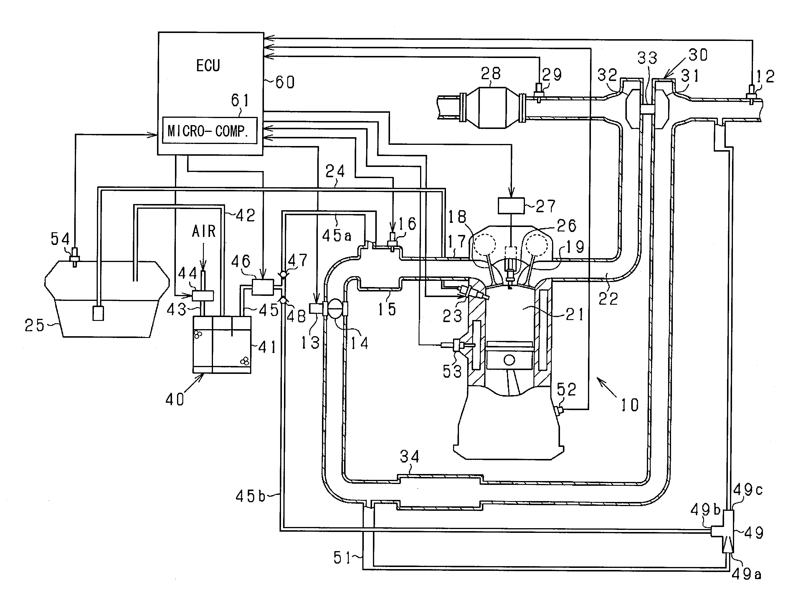
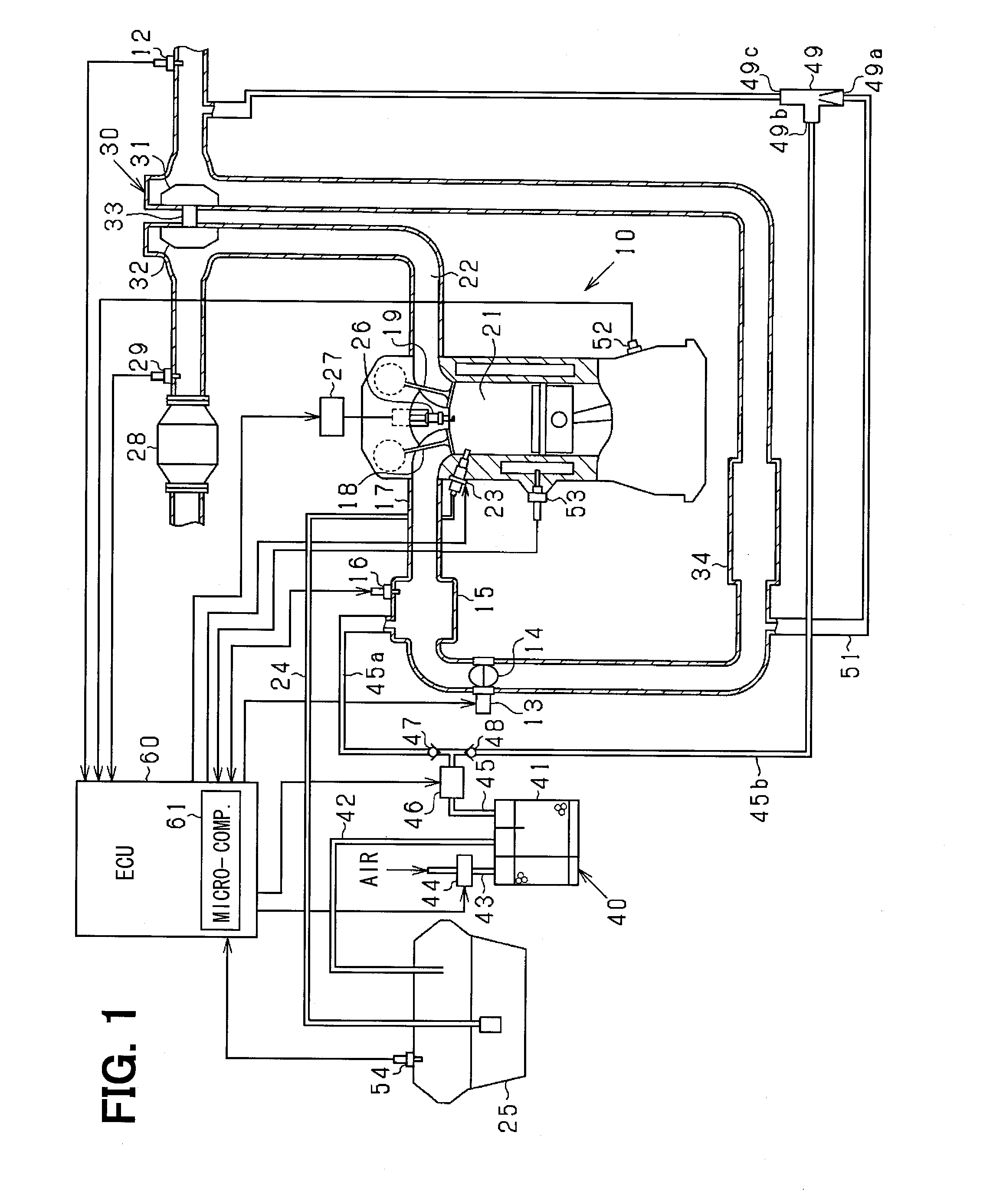
[0053]In the engine 10 shown in FIG. 1, an air-flow meter 12 is provided in an intake-air passage 11 for detecting a flow amount of intake air. A throttle valve 14 (a flow-amount control device) is provided at a downstream side of the air-flow meter 12, wherein an opening degree of the throttle valve 14 is controlled by a throttle actuator 13 composed of, for example, an electric DC motor. The opening degree of the throttle valve 14 (a throttle opening degree) is detected by a sensor (not shown) provided in an inside of the throttle actuator 13. A surge tank 15 provided at a downstream side of the throttle valv...

second embodiment

[0157]In the above first embodiment, the abnormal diagnosis for the air flow is carried out during the engine operation for the vaporized-fuel processing apparatus 40. According to a second embodiment of the present disclosure, the engine has an evaporative leak check module (hereinafter, ELCM) for diagnosing a possible leak of the vaporized fuel. According to the present embodiment, therefore, the abnormal diagnosis for the air flow is carried out by use of the ELCM for the vaporized-fuel processing apparatus 40 not only during the engine operation but also during a period in which the engine operation is stopped. Hereinafter, such portions different from the first embodiment are mainly explained.

[0158]FIG. 11 shows an entire structure for the vaporized-fuel processing system according to the second embodiment of the present disclosure. The ELCM 70 is provided in the air-communication pipe 43 for communicating the canister 41 to the atmospheric air. The ELCM 70 is composed of a swi...


PUM


Abstract

A first purge passage is connected to an intake-air passage at a downstream side of a throttle valve. A second purge passage is connected to the intake-air passage at an upstream side of a supercharging device. A first and a second check valve are respectively provided in the first and second purge passages. A control unit determines to which operating condition (from a first to a third operating condition) engine operation corresponds, based on downstream-side and upstream-side pressure of the throttle valve. A change of in-tank pressure of a fuel tank is detected in a condition that an air-communication valve is closed but a purge control valve is opened. The control unit diagnoses which of the valves is not normally operated and whether such valve is fixed to a valve opened or a valve closed position, based on the change of in-tank pressure for each of engine operating conditions.

Description

CROSS-REFERENCE TO RELATED APPLICATION[0001]This application is based on Japanese Patent Application No. 2012-021501 filed on Feb. 3, 2012, the disclosure of which is incorporated herein by reference.FIELD OF TECHNOLOGY[0002]The present disclosure relates to a vaporized-fuel processing system for an engine, more particularly, a vaporized-fuel processing system according to which vaporized fuel can be purged into an intake-air passage of the engine even during an engine operational period for supercharging intake air into the engine.BACKGROUND[0003]It is known in the art that vaporized fuel generated in a fuel tank is temporally absorbed in a canister and a purge control valve is opened depending on an operational condition of an engine, so that the vaporized fuel absorbed in the canister is supplied into an intake system of the engine together with fresh air because of negative pressure generated by the engine. As a result, the vaporized fuel is processed by combustion in the engine...

Claims


Application Information

Patent Timeline
IPC IPC(8): F02M25/08
CPCF02M25/0809
Inventor TAKEISHI, HIROAKIKATSURAHARA, HIROSHIKOBAYASHI, MITSUYUKI
Owner DENSO CORP
Why Eureka
Try Eureka