Gas Lift System Having Expandable Velocity String

a technology of expandable velocity and lift system, which is applied in the direction of fluid removal, sealing/packing, and wellbore/well accessories, etc., can solve the problems of slowing further production of hydrocarbons, reducing pressure differential, and reducing well production, so as to increase the internal dimension of the string

Active Publication Date: 2013-08-08
WEATHERFORD TECH HLDG LLC
View PDF11 Cites 12 Cited by
  • Summary
  • Abstract
  • Description
  • Claims
  • Application Information

AI Technical Summary

Benefits of technology

[0019]Another technique for expanding the velocity string while deployed in the production tubing uses an expander tool forced through the string's internal passage. The expander tool can be forced by fluid pressure applied down the string's internal passage against the expander tool to move it along the length of the string. Alternatively, coiled rod or tubing dep

Problems solved by technology

Liquids can accumulate in gaseous wells (e.g., natural gas wells and gassy oil wells) and can create backpressure on the formation, which slows further production of hydrocarbons.
Unfortunately, the pressure differential decreases when the reservoir pressure declines over time and when backpressure in the well acts against the reservoir pressure.
This liquid loading phenomenon decreases the production of the well because the weight of the fluid column above the producing formation produces additional backpressure on the reservoir.
For example, mechanical pumps can pump the accumulated liquid L to the surface, but mechanical pumps are typically inefficient in gassy wells.
This increase in pressure differential results in increased flow velocity.
Therefore, the string 40 can quickly become ineffective as gas flow declines.
In particular, the reservoir pressure in the gas well can eventually be depleted over time to the point where there may be insufficient velocity to transport all liquids from the

Method used


Image

  • Gas Lift System Having Expandable Velocity String
  • Gas Lift System Having Expandable Velocity String
  • Gas Lift System Having Expandable Velocity String

Examples


Embodiment Construction

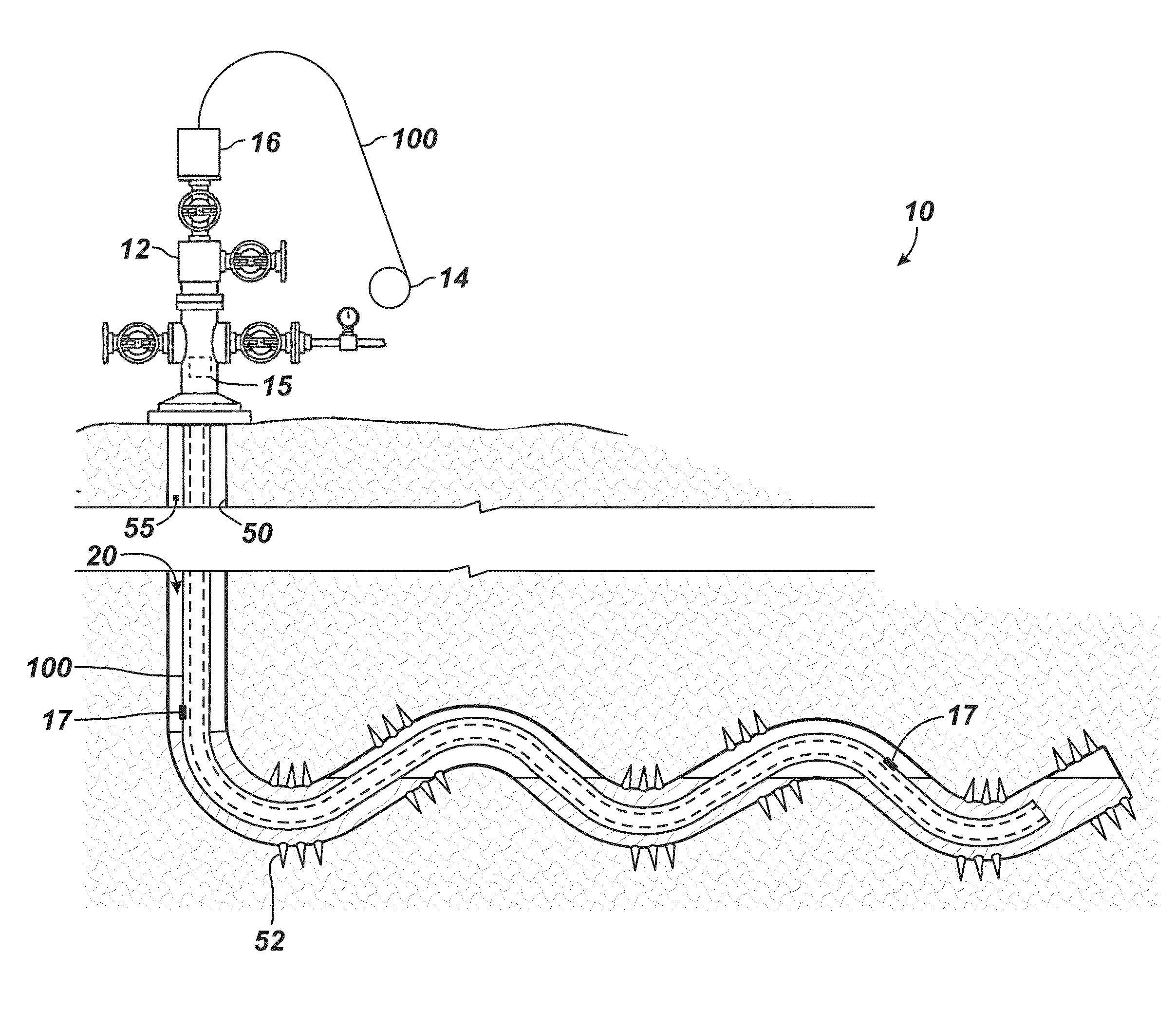
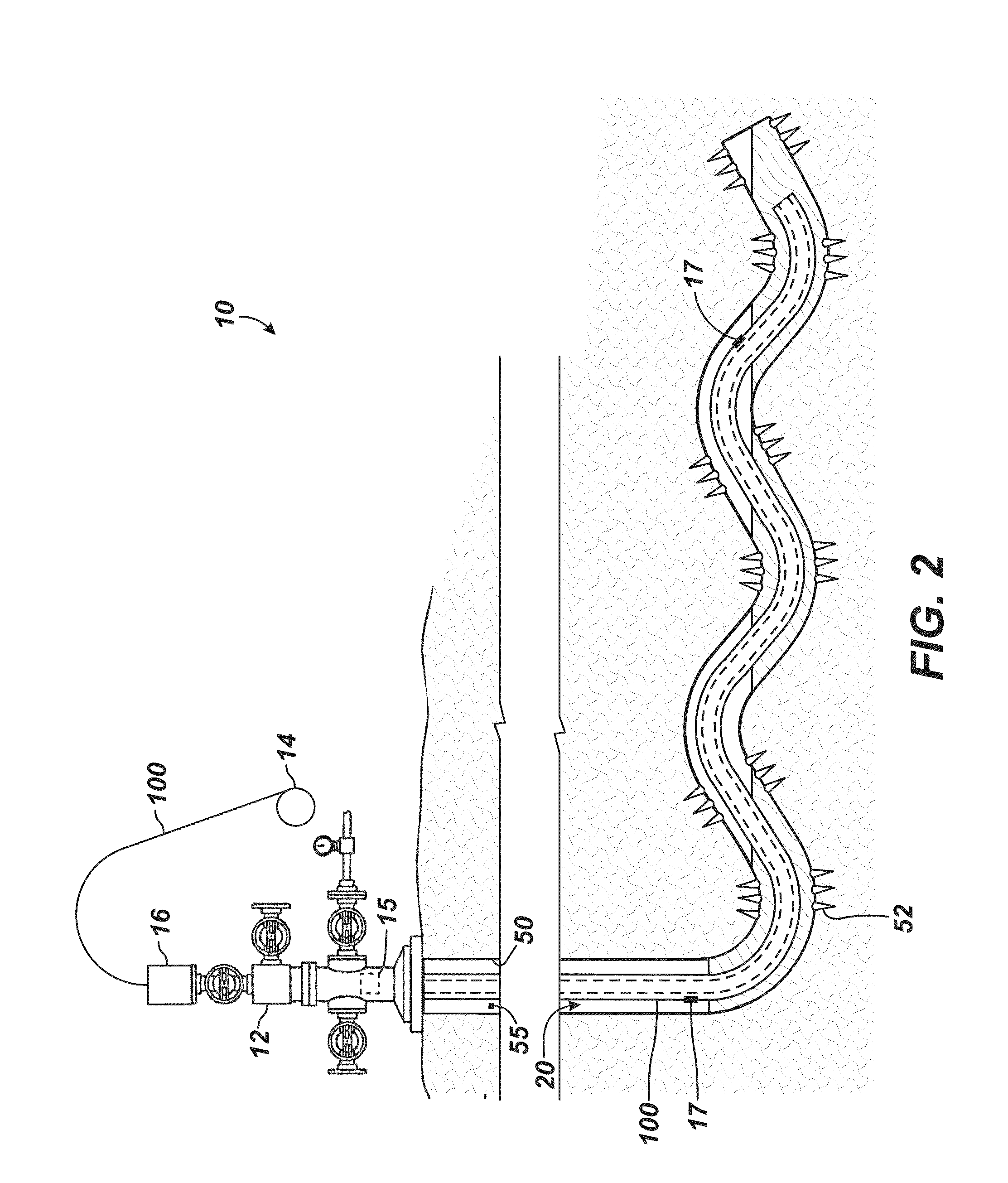
[0034]As noted above, an effective technique for moving liquids through a horizontal gaseous well (e.g., a gas well or a gassy oil well) uses a velocity or dead string, but the string must be configured to produce the desired flow velocity to effectively lift liquids toward the surface. As expected, the string quickly becomes ineffective as the reservoir pressure decreases and gas flow declines. As noted previously, a conventional string installed in a horizontal borehole may be ineffective and may suffer from drawbacks. To overcome such issues, a velocity or dead string disclosed herein installs in a horizontal borehole and has an unexpanded state and one or more expanded states. Depending on the critical flow velocity required to lift liquid in the wellbore toward the surface, operators can initially install the string in its unexpanded state in the production tubing.

[0035]As the reservoir pressure decreases and backpressure increases due to liquid loading, operators can then expa...


PUM


Abstract

A velocity string deploys in production tubing of a gas well (or a gassy oil well) to help lift fluid toward the surface. The velocity string reduces flow area in the production tubing so that a critical flow velocity can be reached to lift liquid. Overtime, the reservoir pressure and resulting gas flow may decrease such that less liquid is produced toward the surface. At such a stage, operators then expand the velocity string to further decrease the flow area in the production tubing, which can produce the needed critical flow velocity to allow produced liquid to be lifted toward the surface.

Description

BACKGROUND[0001]Liquids can accumulate in gaseous wells (e.g., natural gas wells and gassy oil wells) and can create backpressure on the formation, which slows further production of hydrocarbons. To increase the inflow of hydrocarbons into the wellbore, the liquids must be removed so that the backpressure on the formation can be reduced. A number of technologies for dealing with liquid accumulation are used in the art.[0002]To help explain liquid accumulation, the lift system 10 in FIG. 1 has production tubing 30 deployed in a casing 22 of a wellbore 20 for a natural gas well. The casing 22 has perforations 24 so that the natural gas well produces gas and liquid, such as water and hydrocarbon, from the reservoir, and a production tubing packer 32 isolates the casing annulus from the formation fluid (gas G and liquids L). The production tubing 30 conveys the produced fluid to the wellhead 12 at the surface. As is known, the production rate of the natural gas well is a function of the...

Claims


Application Information

Patent Timeline
IPC IPC(8): E21B43/00E21B34/00
CPCE21B34/00E21B43/122E21B43/00E21B43/105E21B43/13
Inventor LANE, WILLIAM C.BANTA, DEBORAH L.
Owner WEATHERFORD TECH HLDG LLC
Why Eureka
Try Eureka