Spark plug

a spark plug and spark plug technology, applied in the field of spark plugs, can solve the problems of deterioration of spark endurance, separation of noble metal tips, and failure of welding strength to cope with a severer working environment of spark plugs, and achieve the effect of improving welding strength

Active Publication Date: 2013-08-08
NGK SPARK PLUG CO LTD
View PDF0 Cites 15 Cited by
  • Summary
  • Abstract
  • Description
  • Claims
  • Application Information

AI Technical Summary

Benefits of technology

[0006]The present invention has been conceived to solve the conventional problems mentioned above, and an object of th

Problems solved by technology

This method can increase the welding strength between the ground electrode and the noble metal tip, but involves a problem of deterioration in spark endurance, since the discharge surface of the noble metal tip contains components of a ground electrode base metal as a result of fusion.
This method, however, involves the following problem: the welding strength between the ground electrode and a central portion of the noble metal tip is weak, and cracking may be generated in the noble metal tip or a fusio

Method used


Image

  • Spark plug
  • Spark plug
  • Spark plug

Examples


first embodiment

A. First Embodiment

[0191]A1. Structure of Spark Plug

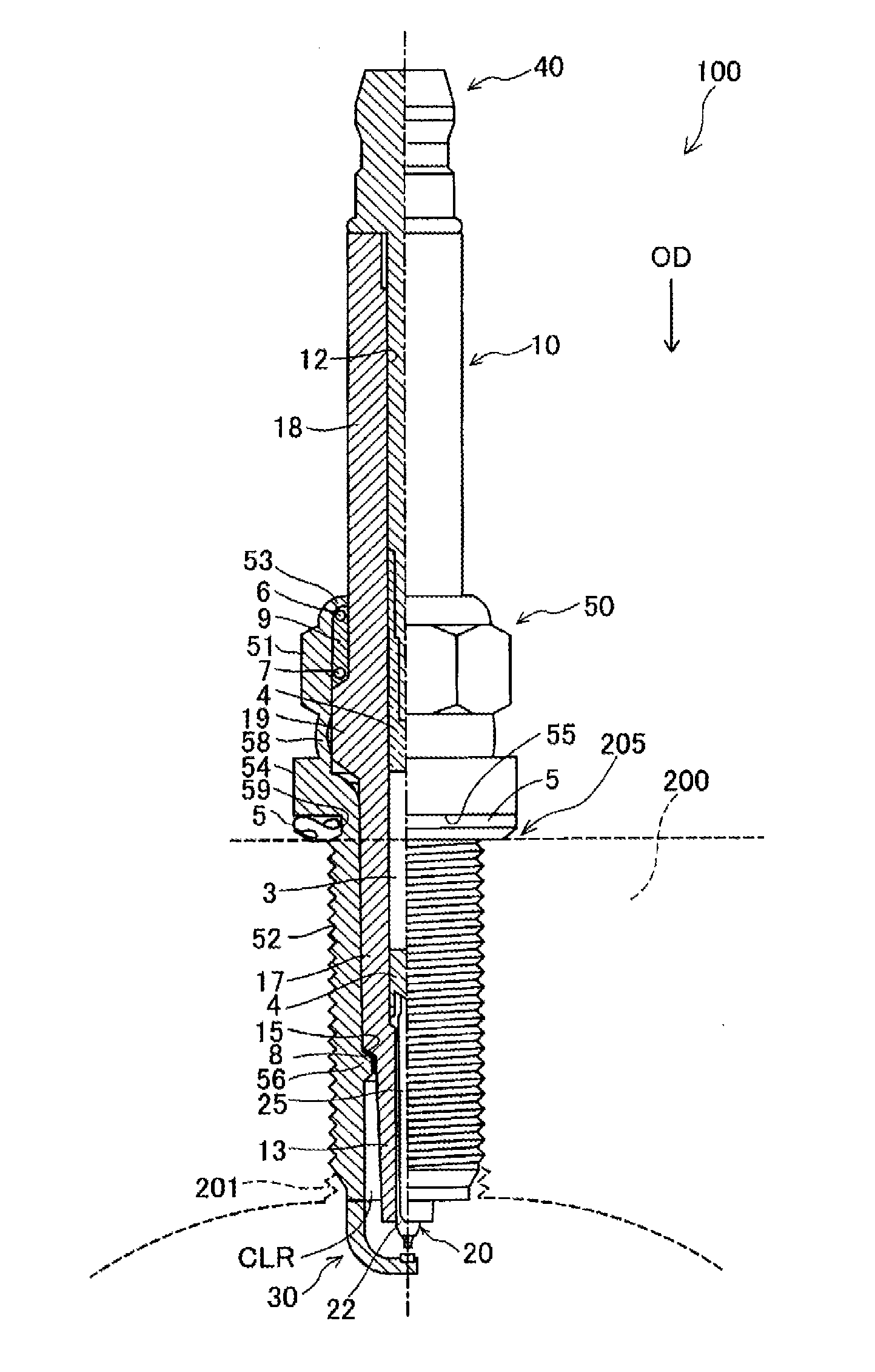
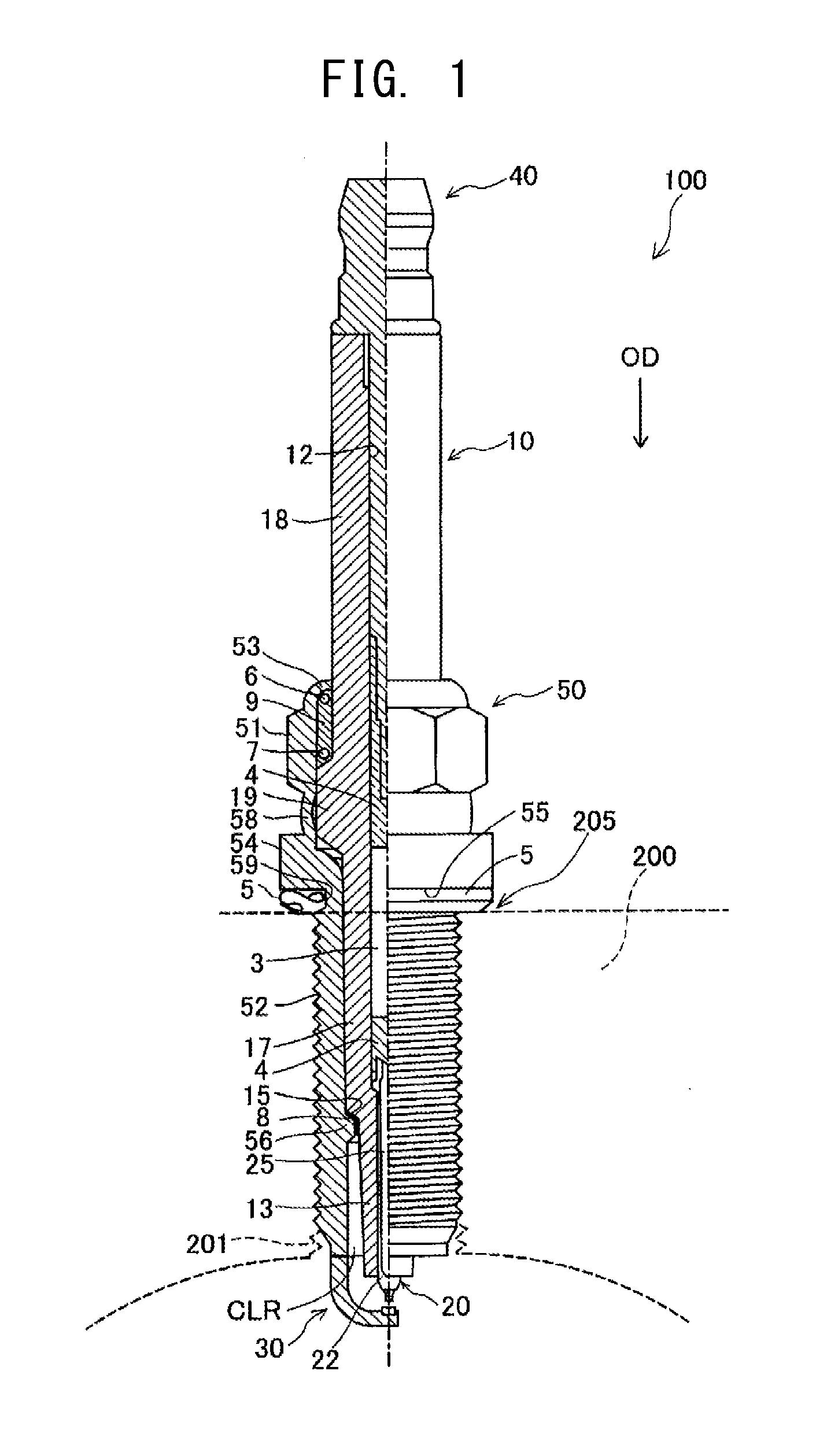
[0192]FIG. 1 is a partially sectional view showing a spark plug 100 according to an embodiment of the present invention. In the following description, an axial direction OD of the spark plug 100 in FIG. 1 is referred to as the vertical direction, and the lower side of the spark plug 100 in FIG. 1 is referred to as the forward side of the spark plug 100, and the upper side as the rear side.

[0193]The spark plug 100 includes a ceramic insulator 10, a metallic shell 50, a center electrode 20, a ground electrode 30, and a metal terminal 40. The center electrode 20 is held while extending in the ceramic insulator 10 in the axial direction OD. The ceramic insulator 10 functions as an insulator, and the metallic shell 50 holds the ceramic insulator 10. The metal terminal 40 is provided at a rear end portion of the ceramic insulator 10. The configuration of the center electrode 20 and the ground electrode 30 will be described in detail late...

second embodiment

B. Second Embodiment

[0218]FIGS. 4(A)-4(C) are sets of explanatory views showing, on an enlarged scale, the distal end portion 33 and its vicinity of the ground electrode 30 in a spark plug 100b according to a second embodiment of the present invention. FIGS. 4(A), 4(B), and 4(C) correspond to FIGS. 3(A), 3(B), and 3(C), respectively. The second embodiment differs from the first embodiment shown in FIG. 3 in that fusion zones 110 and 120 are formed from opposite side surfaces 35 and 36, respectively, of the ground electrode 30. Other configurational features are similar to those of the first embodiment.

[0219]The first fusion zone 110 can be formed through radiation of a high-energy beam from a direction LD1 directed toward the side surface 35 of the ground electrode 30. Similarly, the second fusion zone 120 can be formed through radiation of the high-energy beam from a direction LD2 directed toward the side surface 36 of the ground electrode 30.

[0220]Preferably, as shown in FIG. 4(A)...

third embodiment

C. Third Embodiment

[0229]FIGS. 6(A)-6(C) are sets of explanatory views showing, on an enlarged scale, the distal end portion 33 and its vicinity of the ground electrode 30 in a spark plug 100c according to a third embodiment of the present invention. FIG. 6(A) is a view showing the ground electrode 30 as viewed from a direction directed toward a side surface of the ground electrode 30. FIG. 6(B) is a view showing the ground electrode 30 as viewed from a direction directed toward the distal end surface of the ground electrode 30. FIG. 6(C) is a sectional view taken along line X1-X1 of FIG. 6(A). In other words, FIG. 6(C) shows a section which passes through the center of gravity G of the ground electrode tip 95 and is perpendicular to the axial direction OD.

[0230]In the spark plug 100c, a distal end surface 31 of the ground electrode 30 faces a side surface 93 of the center electrode tip 90. The ground electrode tip 95 is provided on the distal end surface 31 of the ground electrode ...


PUM


Abstract

In a spark plug, a fusion zone where a ground electrode and a noble metal tip are fused together is formed in at least a portion of an interfacial region between the ground electrode and the noble metal tip. When the fusion zone is projected in the axial direction, the projected fusion zone overlaps 70% or more of the area of the noble metal tip. As viewed on a section which passes through the center of gravity of the noble metal tip and is perpendicular to the longitudinal direction of the ground electrode, the relational expression 1.3≦B/A is satisfied, where A is the greatest thickness of the fusion zone along the axial direction, and B is the length from a portion having the greatest thickness of the fusion zone to the inner end of the fusion zone.

Description

FIELD OF THE INVENTION[0001]The present invention relates to a spark plug.BACKGROUND OF THE INVENTION[0002]Conventionally known methods of joining a noble metal tip to a ground electrode of a spark plug are disclosed in, for example, PCT Application Laid-Open No. 2004-517459 and US Patent Application Publication No. 2007 / 0103046.[0003]According to the method disclosed in PCT Application Laid-Open No. 2004-517459, a noble metal tip is completely melted and joined to a ground electrode. This method can increase the welding strength between the ground electrode and the noble metal tip, but involves a problem of deterioration in spark endurance, since the discharge surface of the noble metal tip contains components of a ground electrode base metal as a result of fusion.[0004]Also, according to the method disclosed in US Patent Application Publication No. 2007 / 0103046, a peripheral portion of a noble metal tip is melted, thereby joining the noble metal tip to a ground electrode. This met...

Claims


Application Information

Patent Timeline
IPC IPC(8): H01T13/20
CPCH01T13/20H01T13/32
Inventor SAKAYANAGI, NOBUAKINAKAYAMA, KATSUTOSHI
Owner NGK SPARK PLUG CO LTD
Why Eureka
Try Eureka