Light-emitting diode driving apparatus

Active Publication Date: 2013-08-08
NICHIA CORP
View PDF1 Cites 56 Cited by
  • Summary
  • Abstract
  • Description
  • Claims
  • Application Information

AI Technical Summary

Benefits of technology

[0016]According to this construction, the amount of current on the output line that is detected by the current detection portion can be adjusted to a value that is proportional to the rectified voltage. As a result, the input current of the entire circuit can be a waveform that is proportional to the AC input voltage. Therefore, it is possible to suppress harmonic components.
[0017]In a light-emitting diode driving apparatus according a third aspect of the present invention, a voltage variation suppression signal generation portion can be further provided. The voltage variation suppression signal generation portion is connected in series to the in-series circuit of the first and second LED portions an

Problems solved by technology

On the other hand, after a voltage applied to the LEDs exceeds Vf, an excessive amount of current may flow through the LEDs.
Accordingly, the parts count will increase, and the circuit c

Method used


Image

  • Light-emitting diode driving apparatus
  • Light-emitting diode driving apparatus
  • Light-emitting diode driving apparatus

Examples


Example

First Embodiment

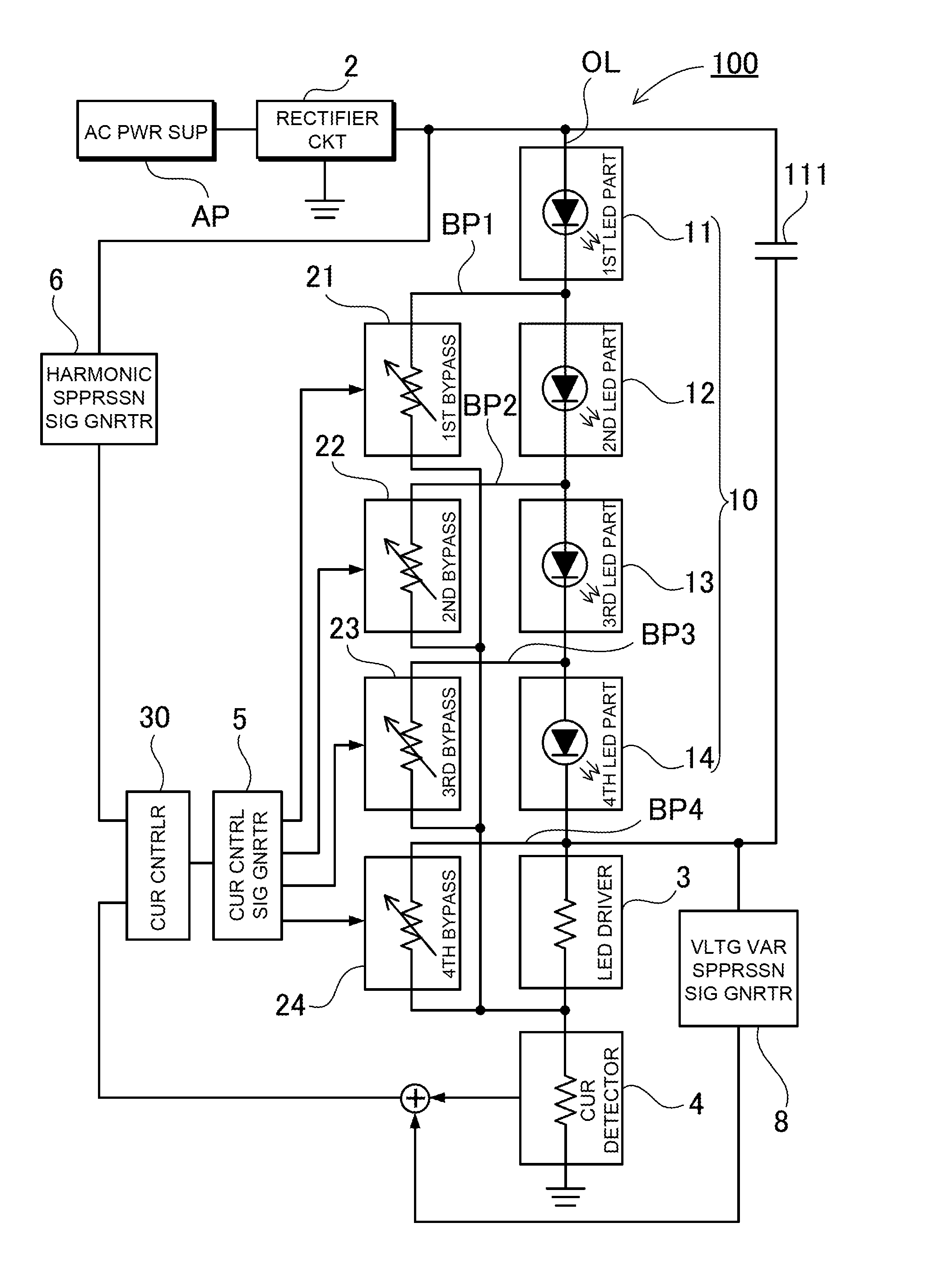
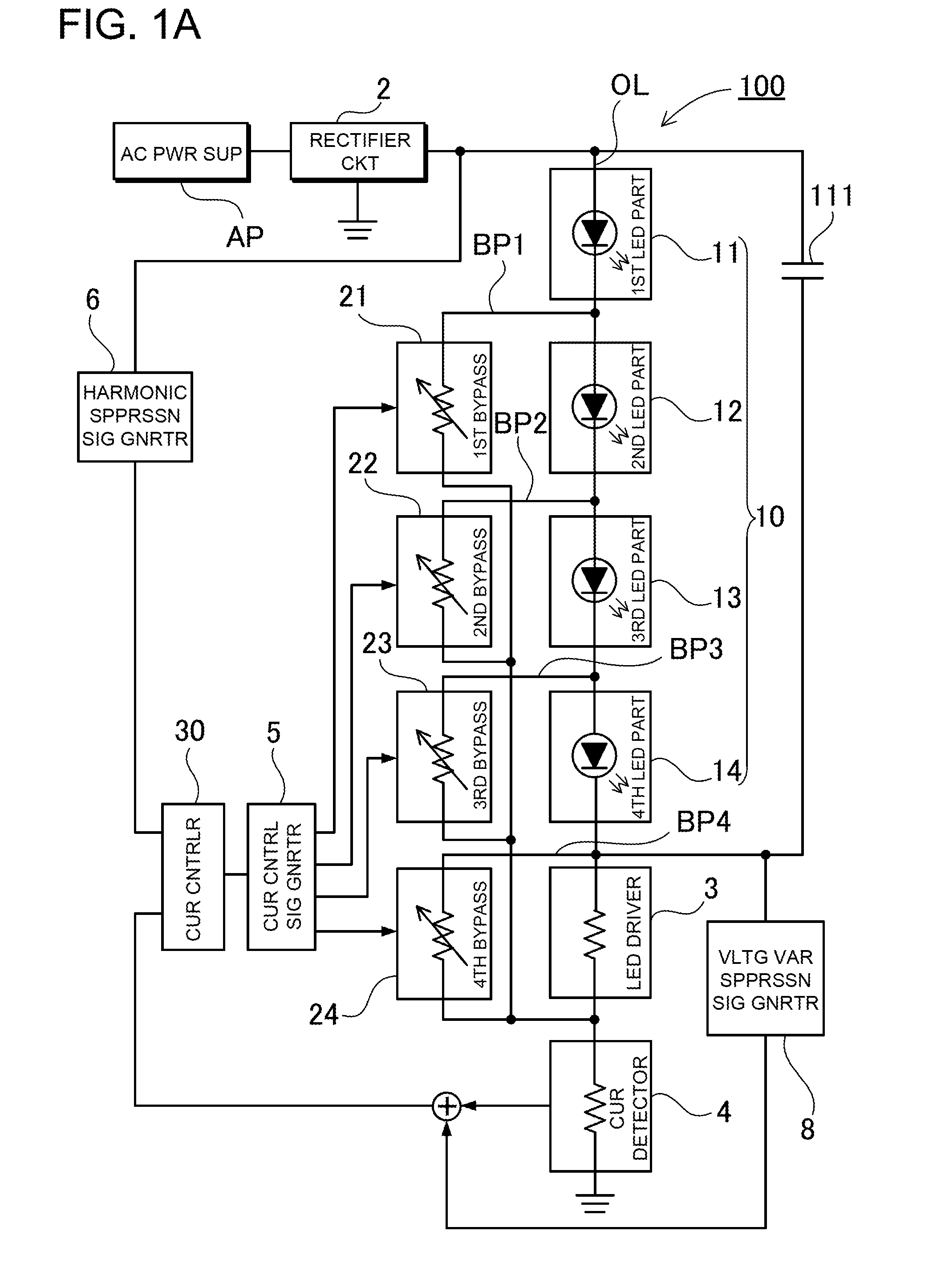
[0057]FIG. 1A is a block diagram showing a light-emitting diode driving apparatus 100 according to a first embodiment. The light-emitting diode driving apparatus 100 includes a rectifying circuit 2, an LED unit 10, first to fourth bypass portions 21 to 24, a current control portion 30, and a current detection portion 4. In the light-emitting diode driving apparatus 100, the rectifying circuit 2, and the LED unit 10 are serially connected to each other through an output line OL. The rectifying circuit 2 is connected to AC power supply AP, and obtains a rectified voltage (pulsating voltage) by rectifying an AC voltage. The LED unit 10 includes a plurality of LED portions. In this embodiment, four LED portions are used as first, second, third and fourth LED portions 11, 12, 13 and 14, which are serially connected to each other. Thus, the first to fourth LED portions compose the LED unit 10. In addition, the LED unit 10, an LED driving portion 3, and the current detectio...

Example

Second Embodiment

[0115]In the foregoing embodiment, it has been described that one first charging / discharging capacitor 111 is connected as the smoothing circuit. However, the present invention is not limited to this. A plurality of capacitors can be connected to further improve the waveform improvement effect. A light-emitting diode driving apparatus 200 according to a second embodiment includes a plurality of capacitors. FIG. 6 is a block diagram of the light-emitting diode driving apparatus 200, which additionally includes a second charging / discharging capacitor 112 connected as the smoothing circuit. FIG. 7A is a diagram showing an exemplary specific circuit of the light-emitting diode driving apparatus 200. FIG. 8 shows the current and voltage waveforms of the first charging / discharging capacitor 111 in this exemplary circuit. FIG. 9 shows the current and voltage waveforms of the second charging / discharging capacitor 112. The second charging / discharging capacitor 112 is connec...

Example

Third Embodiment

[0125]The number of the charging / discharging capacitors is not limited to two. Three or more charging / discharging capacitors can be provided. FIG. 12 is a circuit diagram showing a light-emitting diode driving apparatus 300 according to a third embodiment, which includes three charging / discharging capacitors. A third charging / discharging capacitor 113 is additionally connected in parallel to the first and second LED portions 11 and 12 as shown in this diagram. According to this construction, the ripple factor can be improved similar to the first and second embodiments.

[0126]In particular, the third charging / discharging capacitor 113 is used to be charged when the rectified voltage applied to the third LED portion becomes high so that the third charging / discharging capacitor is discharged to apply a current to the third LED portion 13 when the rectified voltage becomes low. As a result, it is possible to reduce the difference of the current amount in the third LED por...


PUM


Abstract

An apparatus includes first and fourth bypasses, a current detector, and a current controller. The first bypass is connected serially to a first LED, and controls the current amount in the first LED. The fourth bypass is connected serially to a second LED, and controls the current amount in the first and second LEDs. The detector detects current detection signal based on the current amount on an output line along which the first and second LEDs are connected serially to each other. The controller provides control signal for controlling the first and fourth bypasses based on the detection signal. The controller includes one output for providing the control signal. The first and fourth bypasses are connected in parallel to the one output.

Description

BACKGROUND OF THE INVENTION[0001]1. Field of the Invention[0002]The present invention relates to a driving circuit that drives light emitting diodes, and in particular to a light-emitting diode driving apparatus that drives light emitting diodes by using AC power supply.[0003]2. Description of the Related Art[0004]In recent years, significant attention is given to light emitting diodes (hereinafter, occasionally referred to as “LEDs”) as lighting sources. The reason is that LEDs can be driven at low power consumption as compared with filament lamps or fluorescent lamps. LEDs are small, and have shock resistance. In addition, LEDs are less prone to blow out. Thus, LEDs have these advantages.[0005]In the case of lighting sources, it is desirable that commercial AC power for home use is used as power supply for lighting sources. However, LEDs are devices driven by DC power. LEDs emit light only when applied with a current in the forward direction. Also, in the case of LEDs that are cur...

Claims


Application Information

Patent Timeline
IPC IPC(8): H05B37/02
CPCH05B33/083H05B37/02H05B45/48H05B47/10
Inventor SAKURAGI, HARUMIOGURA, WATARUWATANABE, TERUOKITAHARA, MINORU
Owner NICHIA CORP
Why Eureka
Try Eureka