LED circuit arrangement

a technology of led circuits and circuits, applied in the direction of lighting apparatus, electrical equipment, light sources, etc., can solve the problems of limited scalability, complicated circuits, and particularly unsuitable lighting applications, and achieve the effects of reducing the number of circuits, easy setting, and increasing the luminous flux

Active Publication Date: 2013-08-08
KONINKLIJKE PHILIPS ELECTRONICS NV
View PDF5 Cites 73 Cited by
  • Summary
  • Abstract
  • Description
  • Claims
  • Application Information

AI Technical Summary

Benefits of technology

[0046]Furthermore, multiple LED circuit arrangements may be connected in parallel to said power supply to increase the luminous flux.
[0047]The switching frequency and thus the duty cycle of the switching mode operation mainly depends on the operating voltage. Since the current through the first and the second LED unit may differ in the low and high voltage modes, the luminous flux in both modes may differ, resulting in dependence of the luminous flux on the operating voltage. While this may be advantageous in that it enables the luminous flux to be easily set in a certain range, in particular in the case that a non-stabilized power supply is used, the quality of the light output may be impaired.
[0048]According to a further preferred embodiment of the invention, the control unit is configured to adapt the first and/or the second

Problems solved by technology

Certainly, due to the relatively high losses, such an arrangement may be particularly unsuitable for lighting applications, e. g. in combination with high-power LEDs.
However, such circuits typically are elaborate and thus costly.
Additionally

Method used


Image

  • LED circuit arrangement
  • LED circuit arrangement
  • LED circuit arrangement

Examples


Embodiment Construction

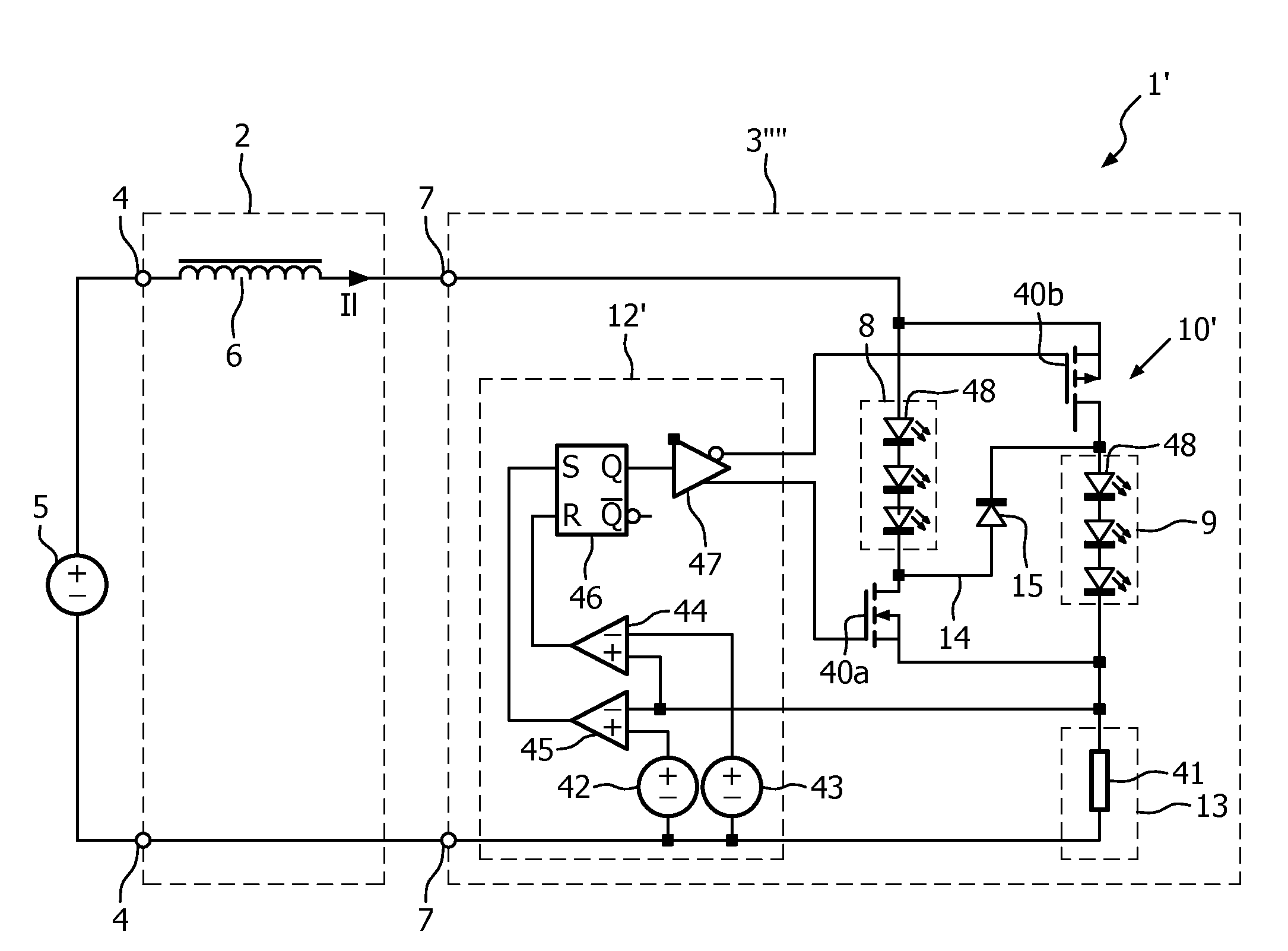
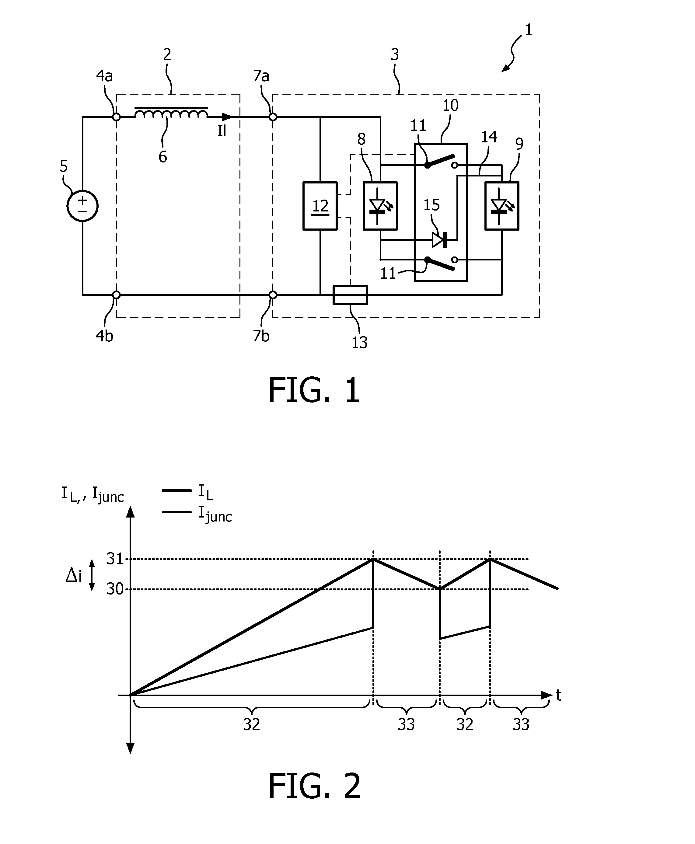
[0060]FIG. 1 shows a schematic circuit diagram of a LED circuit arrangement 1 according to a first embodiment of the present invention. The LED circuit arrangement 1 comprises a LED supply circuit 2 connected with a LED light source 3. The LED light source 3 is formed as a single module or chip, as will be explained in the following with reference to FIG. 2. The LED supply circuit 2 comprises a voltage input 4a and a voltage input 4b, i e. according to the present embodiment two terminals for connection to a voltage supply 5 providing a direct-current voltage of 15 V. The supply 5 may for example be a switching mode power supply unit connected to a corresponding mains line and including a rectifier to provide said direct-current voltage.

[0061]The LED supply circuit 2 further comprises a reactive element 6, i.e. in the present example a coil with an inductance of 100 μH, connected in series between the voltage input 4, and thus the voltage supply 5, and the LED light source 3.

[0062]T...


PUM


Abstract

The invention relates to a LED circuit arrangement (1) with at least a voltage input (4), adapted to provide an operating voltage, a reactive element (6) connected in series with said voltage input (4) and a LED light source (3). To enable the LED circuit arrangement (1) to be driven at an operating voltage, the LED light source (3) comprises a first and a second LED unit (8, 9), each having one light emitting diode, controllable switching means (10) to connect said LED units (8, 9) with said reactive element (6) in a low voltage mode and a high voltage mode and a control unit (12). The LED light source (3) shows a first forward voltage in said low voltage mode and a second forward voltage in said high voltage mode, said second forward voltage being higher than said first forward voltage. The control unit (12) is adapted to control the current through the LED light source (3) by setting the switching means (10) to said low voltage mode when the current, supplied to the LED light source (3), corresponds to a first threshold value (30) and by setting the switching means (10) to the high voltage mode when said supplied current corresponds to a second threshold value (31).

Description

FIELD OF THE INVENTION[0001]The present invention relates to a LED circuit arrangement, a LED light source and a method of operating an LED circuit arrangement. Specifically, the present invention relates to driving an LED circuit arrangement at an operating voltage while providing a safe and cost-efficient setup.BACKGROUND OF THE INVENTION[0002]Light emitting diodes (LEDs) are used for a multitude of applications, including in particular signaling and, nowadays to an increasing extent, general illumination applications. Depending on the application and the type of LED used, various designs of driving circuits for LEDs exist. Due to the exponential dependence between operating current and voltage, similarly to other diodes, LEDs are typically driven with a constant current power-supply unit or driving circuit. Most simply, the driving circuit may consist of a series resistor to limit the maximum current delivered to the light emitting diode in case of a variation of the operating vo...

Claims


Application Information

Patent Timeline
IPC IPC(8): H05B33/08H05B44/00
CPCH05B33/08H05B33/0824H05B45/44H05B45/00
Inventor RADERMACHER, HARALD JOSEF GUNTHERLOPEZ, TONIWENDT, MATTHIAS
Owner KONINKLIJKE PHILIPS ELECTRONICS NV
Why Eureka
Try Eureka