Multiple print head printing apparatus and method of operation

a printing apparatus and print head technology, applied in printing, other printing apparatus, typewriters, etc., can solve the problems of partial vacuum in the plenum, paper jam, skewed or translationally misplaced images, etc., to achieve accurate positioning of printed images, minimize electric field strength, and small tolerance

Active Publication Date: 2013-08-08
DELPHAX TECH
View PDF7 Cites 40 Cited by
  • Summary
  • Abstract
  • Description
  • Claims
  • Application Information

AI Technical Summary

Benefits of technology

[0012]The positioning sub-system can include sensors to track the position of the belt in the transport and transverse directions. Based on transport direction sensor outputs, signals are generated and sent to the print heads to enable accurate positioning of the printed images. Based on transverse direction sensor outputs, a drive for the belt is adjusted to maintain the transverse position of the belt constant to within an acceptably small tolerance. Preferably, each print head has a respective associated belt support roller, the associated belt support roller located on the distal side of the belt from the print head and supporting the belt at a predetermined spacing from the print head. The belt support rollers can be made of conductive material and may be grounded or held at a potential to minimize electric field strength in the region of the inkjet print heads. A reduced electric field strength reduces the chance of particles being attracted by charge on the sheet medium and belt and so inhibits consequent contamination of the print head area.

Problems solved by technology

Problem-free paper transport arrangements for printers are difficult to achieve especially for individual sheets.
Problems that can arise variously with different types of sheet transport arrangement include paper jams, skewed or translationally misplaced images, and lifting or curling of paper away from an underlying platen or belt forming part of the sheet feed arrangement.
One problem with many vacuum belt systems is that the partial vacuum in the plenum may develop air currents tending to flow around the edge of a transported sheet.
The air currents may disturb adjacent air in the gap between the belt and the inkjet print head causing the ink passing across the gap between the print head and the paper to move away from its intended path.
This results in the printed image being distorted.
However, the problem is more serious in the case of printing checks and other transaction materials where, in order to prevent waste, it is desirable to print sheet materials with no margins, and where the time and equipment involved in an extra trimming step are undesirable.
Another problem with such belt vacuum systems arises from the usual manner of supporting the belt.
The reduced suction force can result in a region of the paper sheet lifting or curling at the associated print zone which, in turn, can detract from the printed image quality or cause paper jams.
While this may be satisfactory for single print heads, it is problematic for multiple print heads intended to print combined layer images.
Another problem with roller nips arises particularly in rapid print systems where sheets may be fed at a rate on the order of 700 mm per second.
With multiple print heads at this feed rate, there may not be enough time for ink of a first image to dry by the time the sheet is being grabbed by the roller nip to present it to the next print head for overprinting of a second image.
If the ink is not dry, then there is a risk that the roller nip will smudge the first image.

Method used


Image

  • Multiple print head printing apparatus and method of operation
  • Multiple print head printing apparatus and method of operation
  • Multiple print head printing apparatus and method of operation

Examples


Embodiment Construction

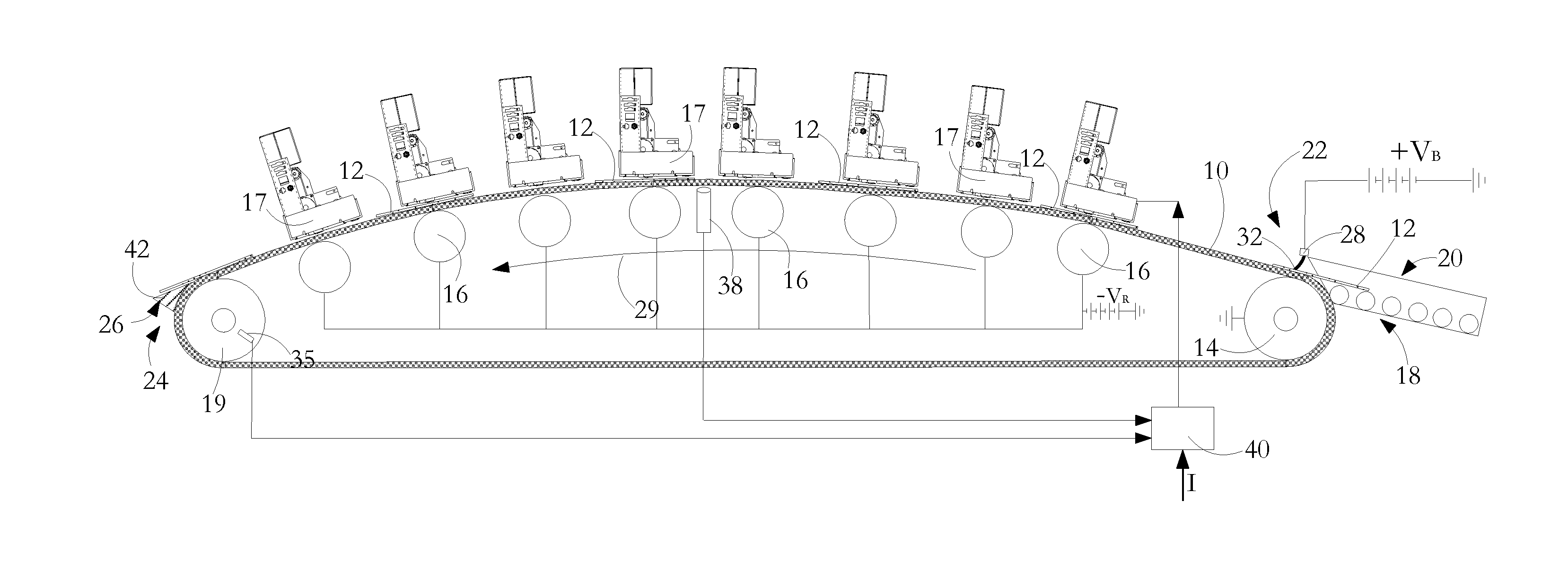
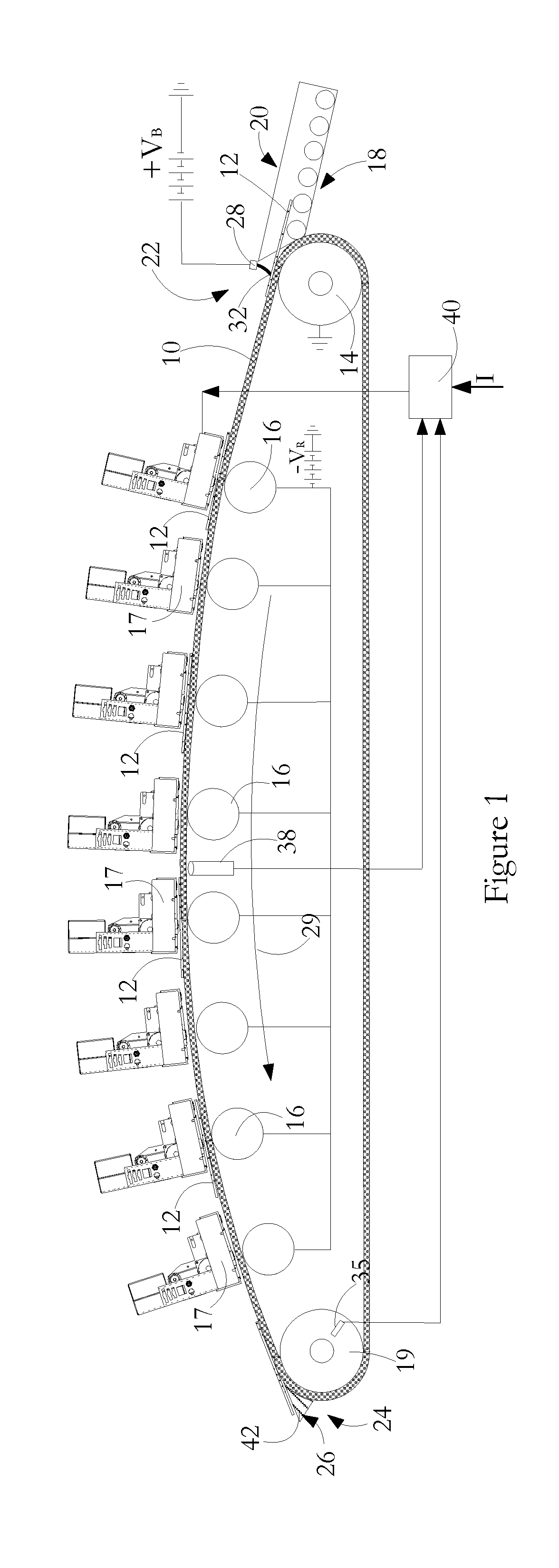
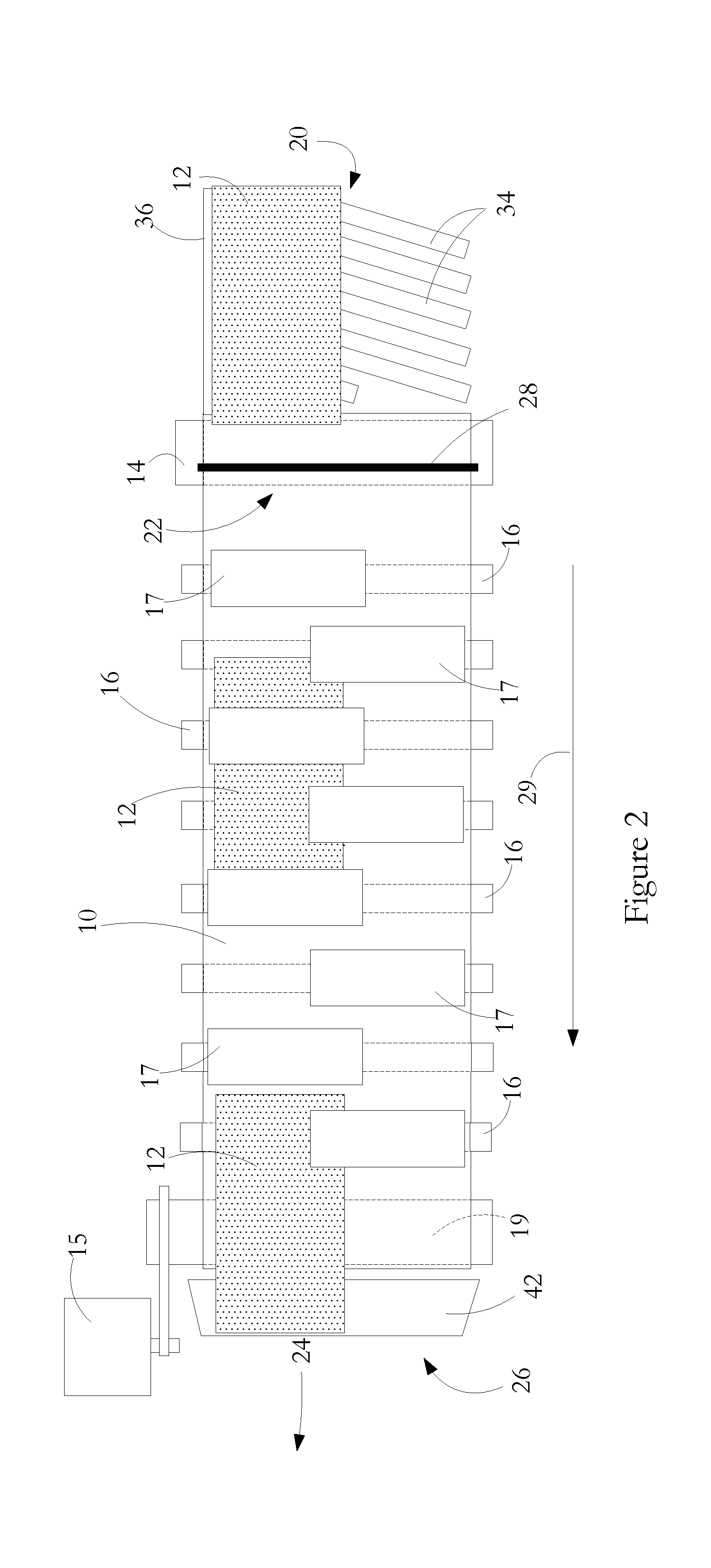
[0022]Referring in detail to FIG. 1, there is shown a continuous belt 10 for transporting paper sheets 12, the belt being driven by a drive roller 19 around a series of idler rollers 16. At an input zone, shown generally as 18, there is a paper alignment sub-system 20 and a charge transfer sub-system 22. At an output zone shown generally as 24, is a paper sheet stripper arrangement 26. Each of the idler rollers 16 is located adjacent a corresponding inkjet print engine 17. Each print engine 17 contains an inkjet print head 13 and mechanical, electrical and fluidic hardware needed to position and operate the print head. The belt is made of Mylar®, an electrical insulator having a high dielectric strength, the belt having a thickness of the order of 0.13 millimetres. While other belt materials are envisioned, Mylar® is particularly suitable owing to its strength, stiffness, transparency, dielectric strength and low leakage. As shown in FIGS. 1 and 2, the inkjet print engine array comp...


PUM


Abstract

A printing apparatus has a series of inkjet print heads spaced from one another in a transport direction. A continuous belt driven around a roller system is used to feed sheet media successively to the print heads so that a partial image printed by one print head is overprinted at a subsequent print head with registration of the partial images. A sheet medium is caused to become electrostatically tacked to the belt by passing the sheet past a charging device. Movement of the belt is tracked by a tracking sub-system and operation of the print heads is coordinated with the tracked belt movement to achieve precise registration of the partial images.

Description

FIELD OF THE INVENTION[0001]This invention relates to a multiple print head printing apparatus and method of operation and has particular application for transporting sheet media to print zones in such a printer.DESCRIPTION OF RELATED ART[0002]There is a need for inkjet printers with multiple print heads. Multiple print heads may be required in the transport direction for achieving high sheet processing speeds, printing an image on a sheet with a large number of inks, and printing characters with a greater ink thickness, and therefore colour density or magnetic ink character recognition (MICR) signal strength, than can be achieved with a single print head. Multiple print heads may also be required extending transverse of a direction of paper transport in order to allow printing of an image having a width greater than can be achieved using a single commercially available print head.[0003]With multiple print heads in the transport direction, it may be required that an image printed at...

Claims


Application Information

Patent Timeline
Patent Type & Authority Applications(United States)
IPC IPC(8): B41J29/38
CPCB41J3/543B41J11/008B41J11/007
Inventor THOMSON, CHRISTOPHERBELBECK, JEFFREYMCCALLUM, ROBERTBELLISARIO, THEODORE
Owner DELPHAX TECH
Why Eureka
Try Eureka