Internal abnormality diagnosis method, internal abnormality diagnosis system, and decision tree generation method for internal abnormality diagnosis of oil-filled electric apparatus utilizing gas concentration in oil

an oil-filled electric apparatus and internal abnormality technology, applied in the field of internal abnormality diagnosis system, decision tree generation method for internal abnormality diagnosis of oil-filled electric apparatus utilizing gas concentration in oil, can solve the problem of limited number of diagnoses which each diagnostic specialist can deal with, and affecting the accuracy of diagnosis. the effect of high accuracy

Active Publication Date: 2013-08-08
KANDEN ENG
View PDF0 Cites 6 Cited by
  • Summary
  • Abstract
  • Description
  • Claims
  • Application Information

AI Technical Summary

Benefits of technology

[0155]The abnormality diagnosis method of an oil-filled electric apparatus according to the present invention as above can analyze historical abnormality case data with high accuracy by employing a method for generating a decision tree on the basis of the discretized data on which specific data processing is performed. Therefore, the abnormality diagnosis method according to the present invention has a diagnostic accuracy equal to or higher than that of a diagnostic specialist having reached a certain level and is highly effective as diagnosis using a machine in a method of analysis utilizing gas concentration in oil.
[0156]Further, it can be expected that the abnormality predictive diagnosis method of an oil-filled electric apparatus according to the present invention performs predictive diagnosis of an internal abnormality which may occur in the future with high accuracy by employing the specific decision tree generation method with respect to the predicted concentrations of the respective gas species which are predicted using the specific regression lines to thereby determine the type of the internal abnormality of the determination target apparatus.

Problems solved by technology

However, in such an analysis method, since a diagnostic specialist performs the estimation from the measured data on the basis of past cases by using his / her knowledge obtained from experience as a criterion for determination, a result of the diagnosis may vary due to a difference in the level of knowledge or experience between diagnostic specialists.
Further, there is a limit on the number of diagnoses which each diagnostic specialist can deal with, and it takes time to deal with a huge number of diagnoses.
Therefore, replacement or repair of an oil-filled electric apparatus may not be able to be performed at an appropriate time.
Further, it requires a considerable amount of time to train a diagnostic specialist of a certain level, and a heavy burden is therefore imposed on skilled diagnostic specialists in the present circumstances.
Therefore, this method diverges from a determination method by a diagnostic specialist, and therefore has a limit on accuracy as diagnosis using a machine.
Further, although various proposals have been made regarding a diagnosis method and a prediction method using a decision tree (see Patent Documents 1 and 2, for example), a method using a decision tree that can be applied to analysis of gas in oil has not yet been proposed, and a development of such a method has therefore been expected.

Method used


Image

  • Internal abnormality diagnosis method, internal abnormality diagnosis system, and decision tree generation method for internal abnormality diagnosis of oil-filled electric apparatus utilizing gas concentration in oil
  • Internal abnormality diagnosis method, internal abnormality diagnosis system, and decision tree generation method for internal abnormality diagnosis of oil-filled electric apparatus utilizing gas concentration in oil
  • Internal abnormality diagnosis method, internal abnormality diagnosis system, and decision tree generation method for internal abnormality diagnosis of oil-filled electric apparatus utilizing gas concentration in oil

Examples


first embodiment

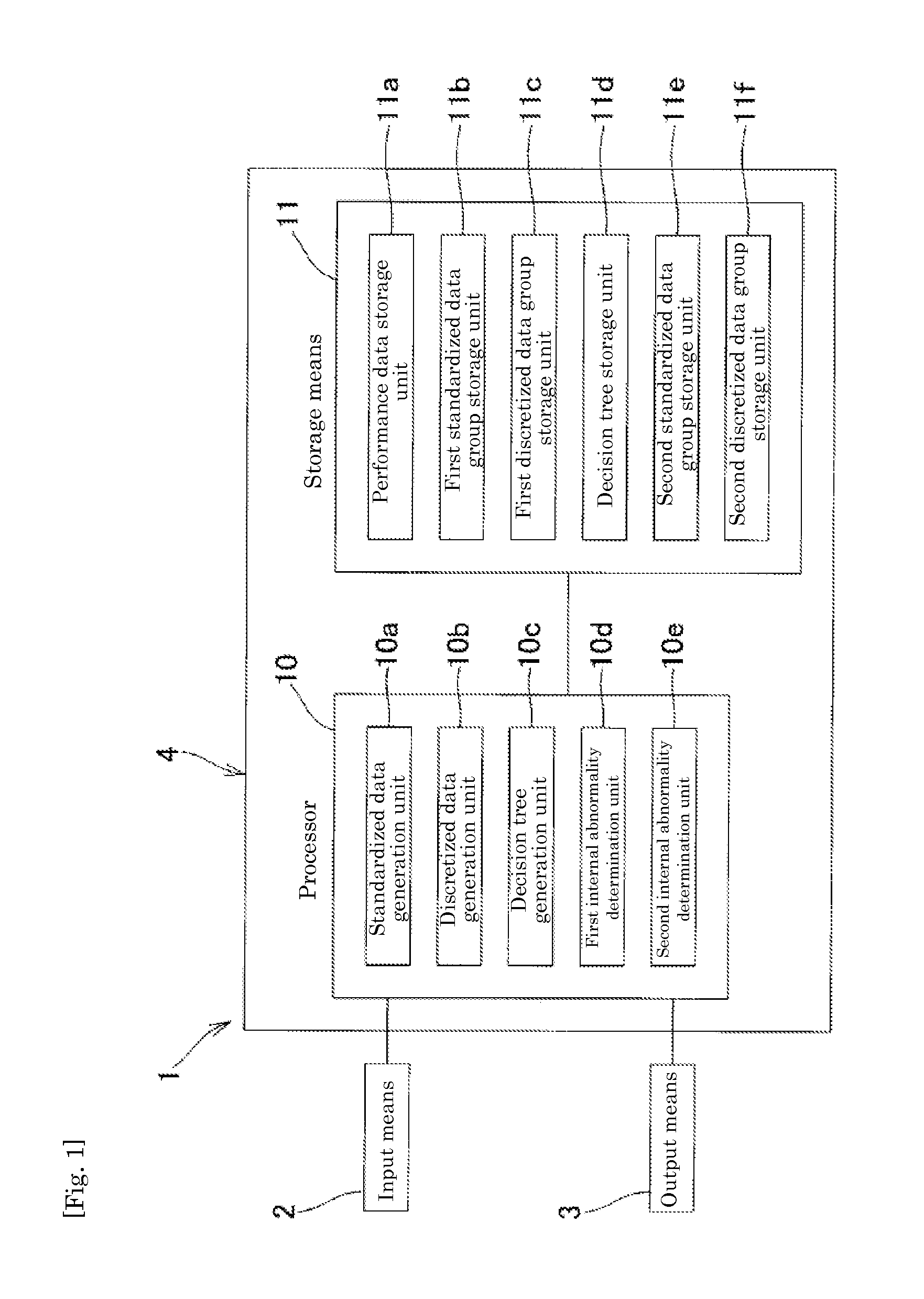
[0177]FIG. 1 is a block diagram illustrating a main configuration of a representative abnormality diagnosis system for performing an abnormality diagnosis method of an oil-filled electric apparatus in a first embodiment of the present invention. As shown in FIG. 1, an abnormality diagnosis system 1 is provided with input means 2, output means 3, and a computer 4. The computer 4 is provided with a processor 10 and storage means 11. The processor 10 is mainly composed of a microprocessor, and includes a storage unit (not shown) which is composed of RAM and ROM. In the processor 10, programs which define procedures for various general processing operations and a procedure for executing a later-described diagnosis method of the present invention and the like and processing data are stored.

[0178]The processor 10 is provided with a standardized data generation unit 10a, a discretized data generation unit 10b, a decision tree generation unit 10c, a first internal abnormality determination ...

second embodiment

(Second Embodiment) Fuzzy Decision Tree

[0224]Next, the second embodiment of the present invention will be described. The present embodiment has the same configuration as the configuration of the first embodiment excepting that a decision tree that is generated on the basis of certainty factors (hereinafter, also referred to as a fuzzy decision tree) and a discretized data group of determination target gases both of which will be described later are used. Therefore, the same figures and the same reference numerals will be used to refer to the same parts as those described in the first embodiment, and a detailed description thereof will be omitted.

[0225]When a fuzzy decision tree is used, a discretized data group that is generated in step S203 shown in FIG. 4 is different from the discretized data group in the first embodiment.

[0226]That is, in the second embodiment, in the discretized data generation unit 10b, on the basis of the standardized data group of each of the abnormality cas...

third embodiment

(Third Embodiment) Abnormality Predictive Diagnosis Method

[0233]Next, the third embodiment of the present invention will be described.

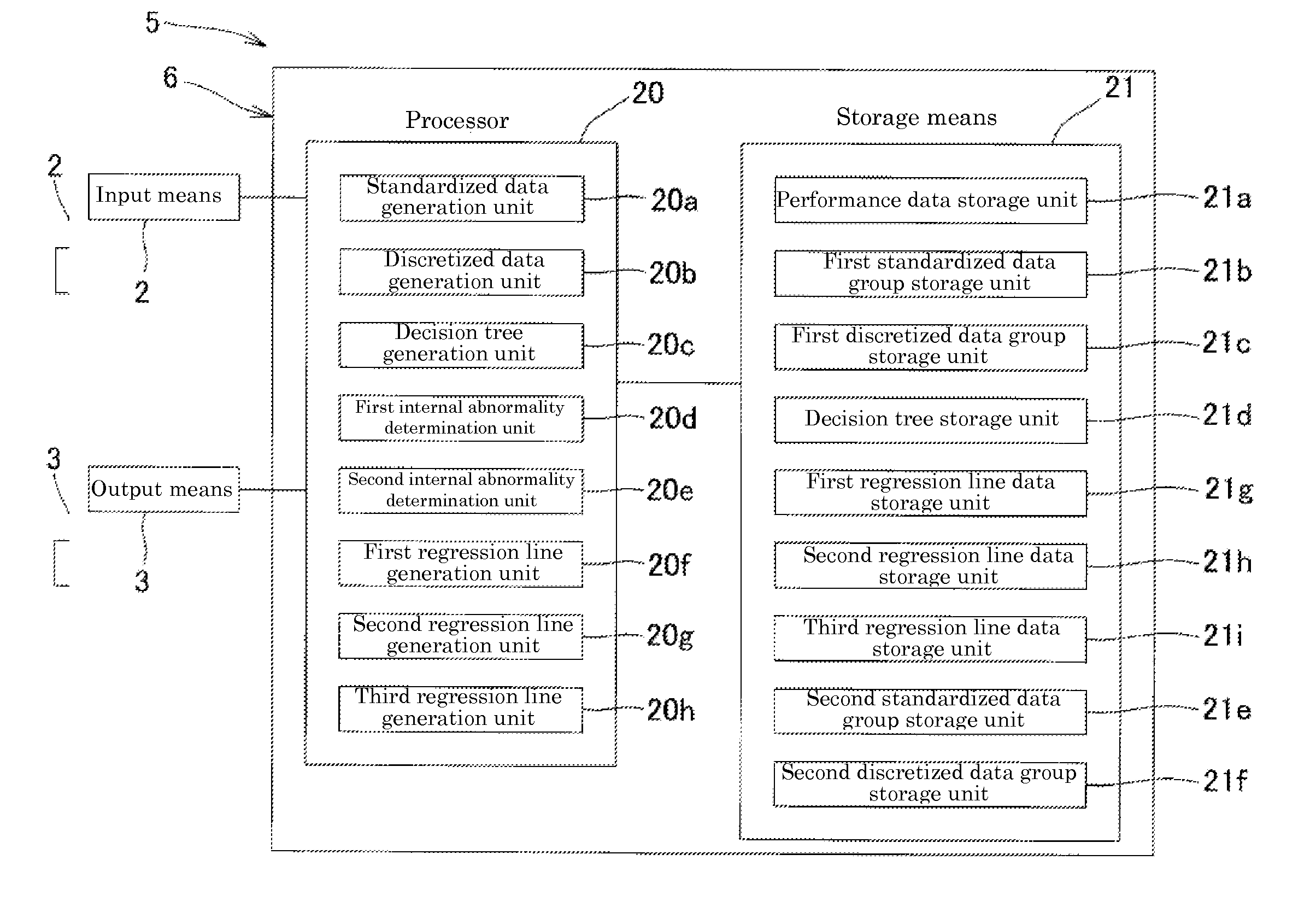
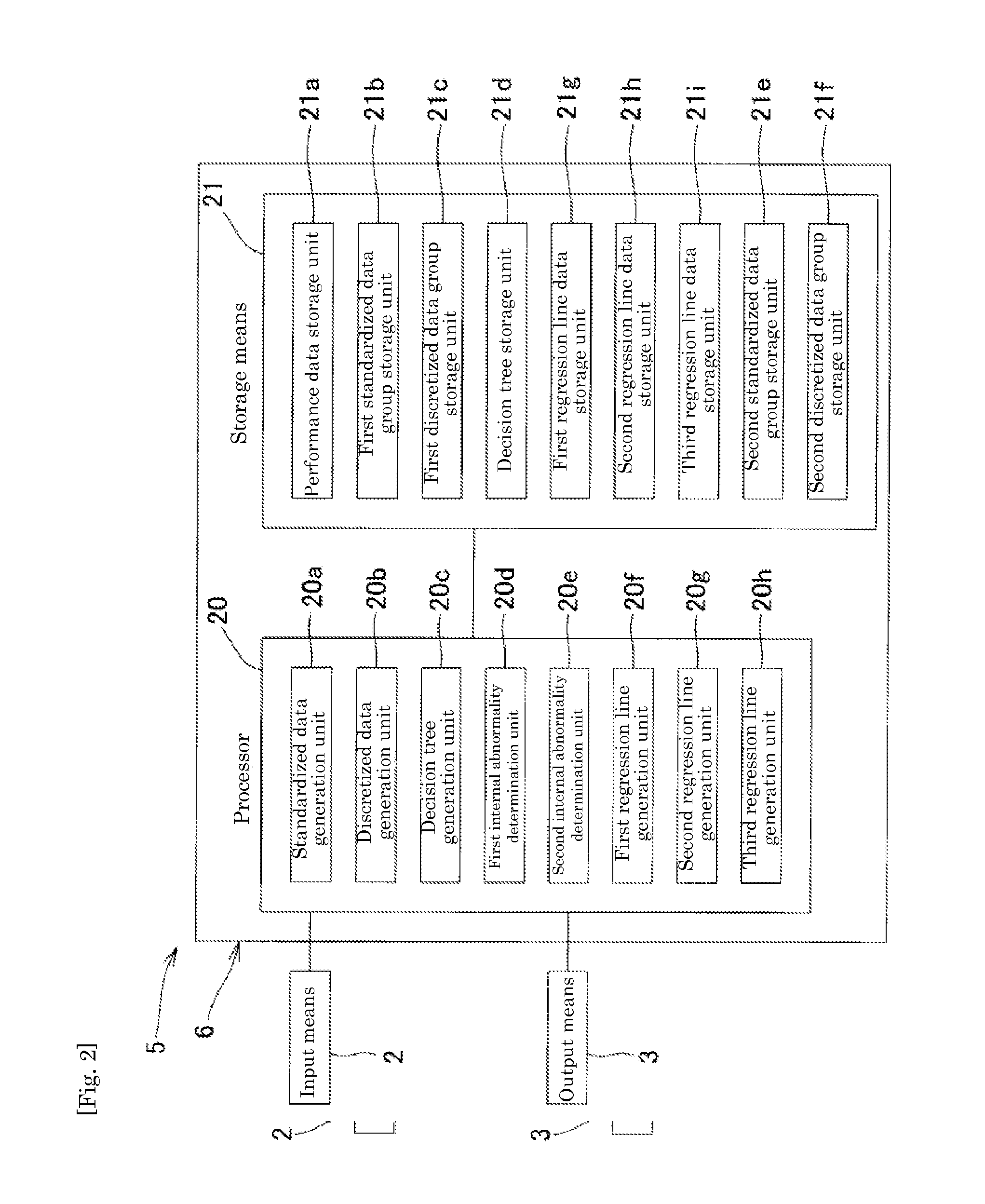
[0234]FIG. 2 is a block diagram illustrating a main configuration of a representative abnormality predictive diagnosis system for performing an abnormality predictive diagnosis method of an oil-filled electric apparatus according to the present invention in which a configuration for predicting the concentrations of the determination target gas species is added to the system configuration shown in FIG. 1. Therefore, the configurations of the units 20a to 20e and 21a to 21f in FIG. 2 are respectively the same as the configurations of the units 10a to 10e and 11a to 11f in FIG. 1.

[0235]Further, FIG. 5 is a schematic flow chart illustrating a flow from input of the concentrations of the determination target gases until obtaining a result of the abnormality predictive diagnosis. As shown in FIG. 5, the present embodiment is completely the same as the first...


PUM


Abstract

An object is to provide an internal abnormality diagnosis method, an internal abnormality diagnosis system and a decision tree generation method for internal abnormality diagnosis of an oil-filled electric apparatus utilizing gas concentration in oil and having a diagnostic accuracy equal to or higher than that of a diagnostic specialist having reached a certain level. The present invention provides a method for generating a decision tree for determining the type of an internal abnormality of an oil-filled electric apparatus using a computer. In the decision tree generation method, the computer generates a standardized data group by converting concentrations of a plurality of gas species dissolved in an insulating oil in an oil-filled electric apparatus into ratios for each abnormality case, generates a discretized data group by converting the ratios of the concentrations of the gas species, the ratios constituting the standardized data group, into a plurality of discretized attributes using predetermined thresholds which are set for the respective gas species, and generates a decision tree for determining the type of an internal abnormality of the oil-filled electric apparatus by analysis using specific formulae on the basis of the discretized data group.

Description

TECHNICAL FIELD [0001]The present invention relates to an internal abnormality diagnosis method, an internal abnormality diagnosis system, and a decision tree generation method for internal abnormality diagnosis of an oil-filled electric apparatus utilizing gas concentration in oil.BACKGROUND ART [0002]There has been widely used a method of analysis using gas concentration in oil as a maintenance method for an oil-filled electric apparatus. For example, when an abnormality occurs inside an oil-filled electric apparatus such as a transformer which is in operation, there is used a so-called gas pattern method (Non Patent Document 1) or the like in which the gas concentration in oil of a sample oil which is taken from the oil-filled electric apparatus is measured, a detail and a location of the abnormality are estimated from the type of gas in oil and the concentration pattern thereof on the basis of past cases.[0003]However, in such an analysis method, since a diagnostic specialist pe...

Claims


Application Information

Patent Timeline
Patent Type & Authority Applications(United States)
IPC IPC(8): G06N5/02
CPCG06N5/02G01N33/2841
Inventor KAWACHI, FUMIOYAMAKOSHI, MASANORIKASAOKA, MAKOTO
Owner KANDEN ENG
Why Eureka
Try Eureka