Blast-resistant vehicle hull

a technology for vehicles and hulls, applied in the field of vehicles, can solve problems such as unacceptable rollover risks, and achieve the effect of reducing the energy transfer of shock waves

Inactive Publication Date: 2013-08-15
FORD GLOBAL TECH LLC
View PDF1 Cites 38 Cited by
  • Summary
  • Abstract
  • Description
  • Claims
  • Application Information

AI Technical Summary

Benefits of technology

[0011]In another embodiment, a vehicle hull comprises a first plate, a second plate attached to the first plate along a joint, and a rib attached to the first and second plates. The rib projects generally perpendicular from the second plate a distance sufficient to cause a shock wave to separate from the hull after passing the joint, thereby reducing energy transfer from the shock wave

Problems solved by technology

One of the challenges in designing a military vehicle is to achieve the proper balance between crew protection (survivability) and mobility.
Increased armor weight and greater ground clearance may result in the vehicle center-of-gravity being so high as to cause an unacceptable roll-over risk when travelling over uneven terrain.

Method used


Image

  • Blast-resistant vehicle hull
  • Blast-resistant vehicle hull
  • Blast-resistant vehicle hull

Examples


Embodiment Construction

[0029]As required, detailed embodiments of the present invention are disclosed herein; however, it is to be understood that the disclosed embodiments are merely exemplary of the invention that may be embodied in various and alternative forms. The figures are not necessarily to scale; some features may be exaggerated or minimized to show details of particular components. Therefore, specific structural and functional details disclosed herein are not to be interpreted as limiting, but merely as a representative basis for teaching one skilled in the art to variously employ the present invention.

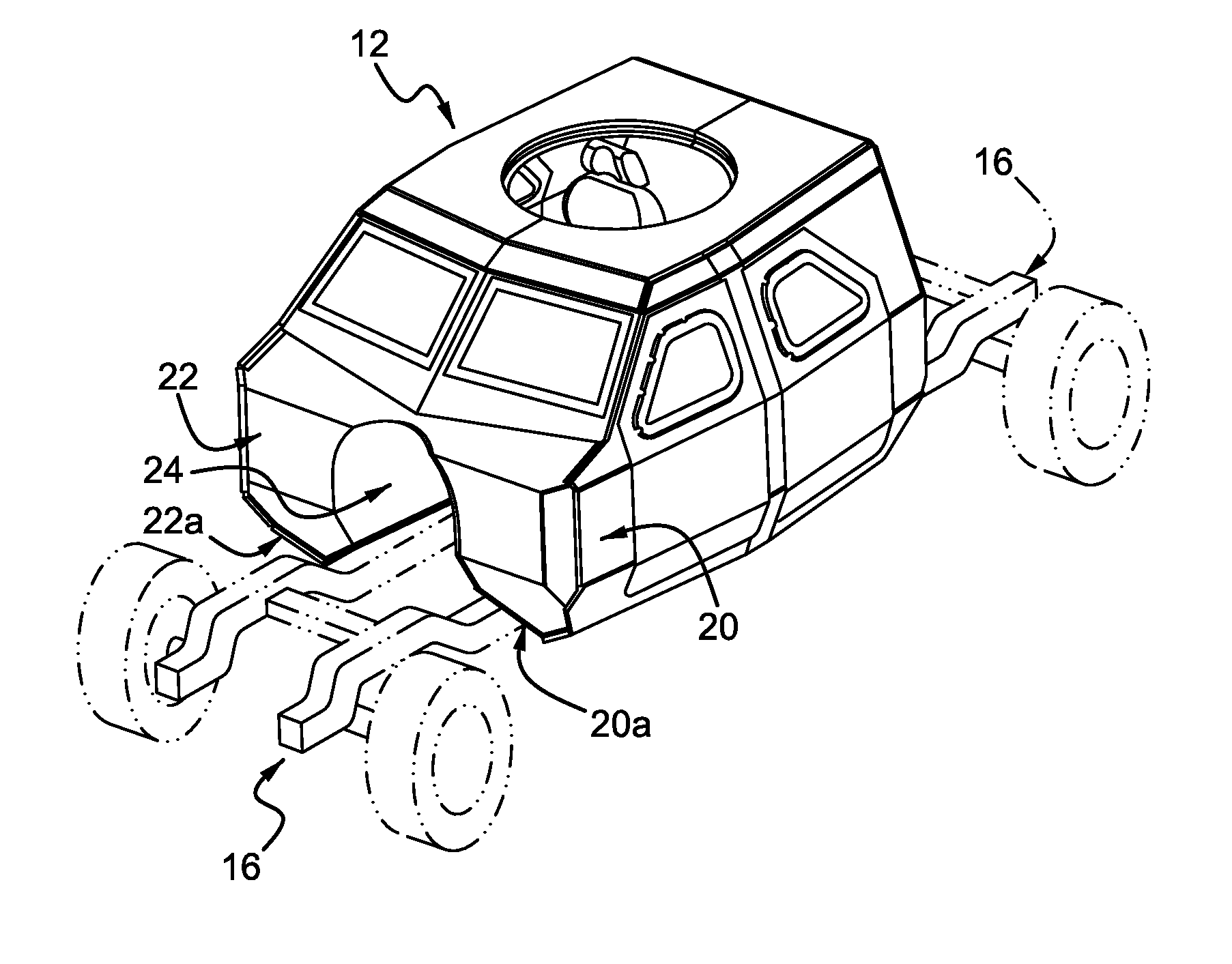
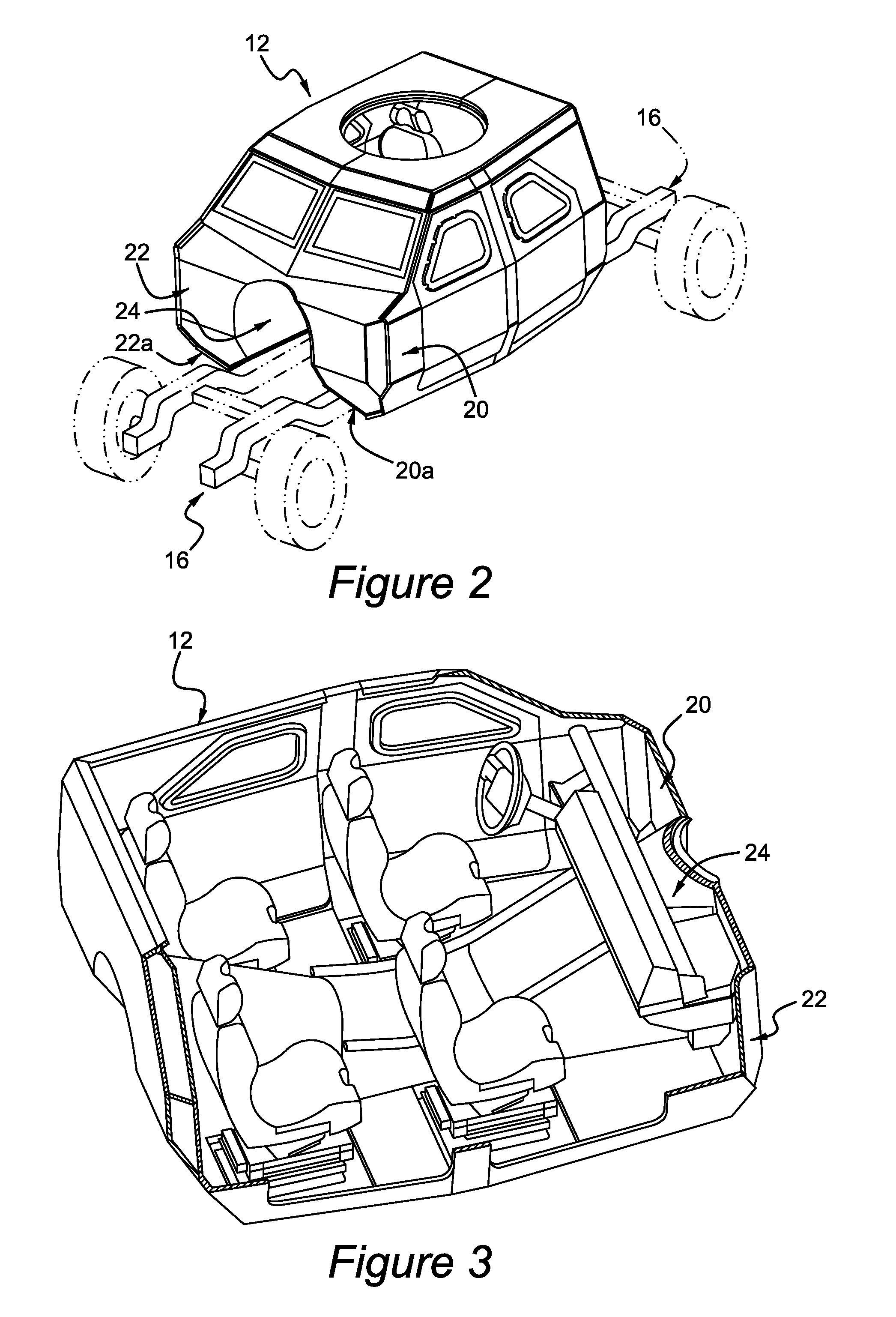
[0030]As seen in FIGS. 2-5, a military vehicle 10 intended for use in a combat zone includes a blast-resistant hull 12 mounted to a frame 14. Suspension and powertrain components are schematically indicated at 16, and may include any number and combination of wheels and / or tracks (not shown). Hull 12 is depicted equipped with four crew seats such as may be the case if the hull forms a crew cab of...


PUM


Abstract

A vehicle hull has a longitudinal blast mitigation duct formed between left and right hull portions. The duct includes a first section oriented at a first angle to a longitudinal reference line, and a second section adjacent to the first section and oriented at a second angle to the reference line. The second angle is greater than the first angle to form a diverging surface for a shock wave travelling from the first to the second section. The blast mitigation duct further comprises a second, rearward-oriented diverging surface for a shock wave travelling rearward along the hull. A rib projects generally perpendicular from a joint between the first and second sections and is configured to initiate separation of the shock wave from the hull, thereby reducing the amount of energy transferred to the hull.

Description

CROSS-REFERENCE TO RELATED APPLICATIONS[0001]This application claims the benefit of U.S. Provisional Application Nos. 61 / 598,517 filed Feb. 14, 2012, and 61 / 601,206 filed Feb. 21, 2012, the disclosures of which are incorporated in their entirety by reference herein.TECHNICAL FIELD[0002]The disclosure relates to vehicles, such as military vehicles, that may be subjected to blasts originating beneath or closely adjacent to the vehicle. More specifically, the disclosure relates to a vehicle hull geometry and method of construction providing improved protection from such blasts.BACKGROUND[0003]Military vehicles used in combat zones must provide ballistic and blast protection for occupants of the vehicle's crew compartment. One of the challenges in designing a military vehicle is to achieve the proper balance between crew protection (survivability) and mobility.[0004]Good mobility generally calls for a vehicle to be lightweight and to have a relatively low center-of-gravity. To achieve a...

Claims


Application Information

Patent Timeline
Patent Type & Authority Applications(United States)
IPC IPC(8): F41H7/00
CPCF41H7/044F41H7/042
Inventor HENKER, LYNDON SCOTTWETTLAUFER, EDWARD F.CUPKA, JR., RICHARD D.SLEVIN, DENNIS G.
Owner FORD GLOBAL TECH LLC
Why Eureka
Try Eureka