Optical cross-coupling mitigation system for multi-wavelength beam combining systems

a technology of optical cross-coupling and beam combining, which is applied in the field of laser systems, can solve the problems of poor spectral utilization, high utilization, and may not be optimal brightness of these systems, and achieve the effect of high brightness, power and efficient multi-wavelength beam combining system

Active Publication Date: 2013-08-15
PANASONIC OF NORTH AMERICA
View PDF4 Cites 37 Cited by
  • Summary
  • Abstract
  • Description
  • Claims
  • Application Information

AI Technical Summary

Benefits of technology

[0008]A wavelength beam combining system comprising a plurality of emitters, such as diode elements, are combined using a dispersive element to form a multi-wavelength beam. Each emitter in the system individually resonates, and is stabilized through wavelength specific feedback from a common partially reflecting output coupler that is filtered by the dispersive element along a beam combining dimension, and wherein any cross-talk between feedback beams is mitigated using a non-slit cross-coupling mitigating optical system. In one embodiment this system comprises f

Problems solved by technology

Furthermore, when broad-area laser elements are used the spectral utilization is poor.
Furthermore, since beam combining is performed along the stacking dimension or near

Method used


Image

  • Optical cross-coupling mitigation system for multi-wavelength beam combining systems
  • Optical cross-coupling mitigation system for multi-wavelength beam combining systems
  • Optical cross-coupling mitigation system for multi-wavelength beam combining systems

Examples


Embodiment Construction

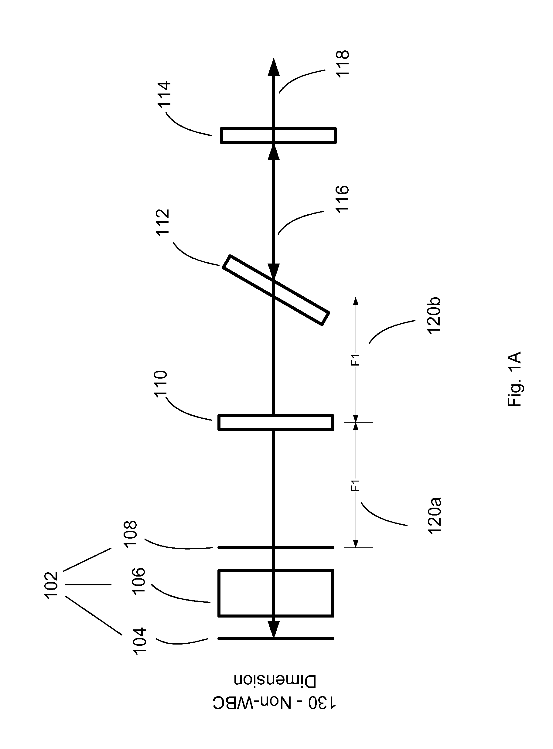
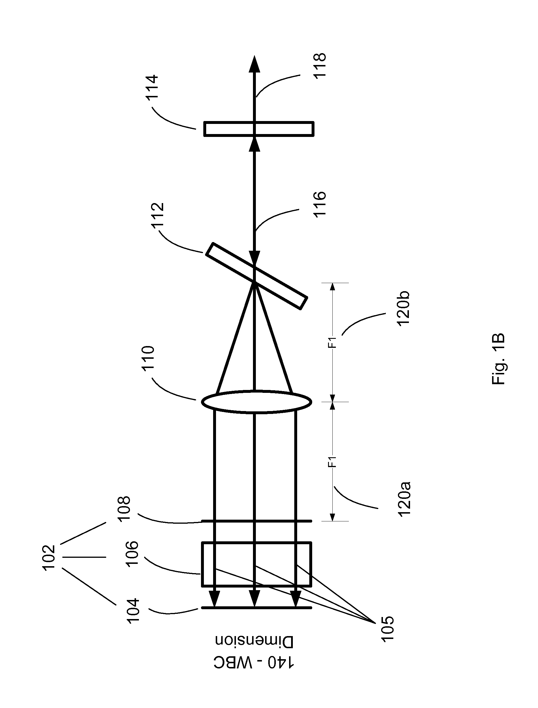
[0012]Aspects and embodiments relate generally to the field of scaling laser sources to high-power and high-brightness using wavelength beam combining techniques. More particularly, methods for increasing brightness, stability, and effectiveness of wavelength beam combining systems.

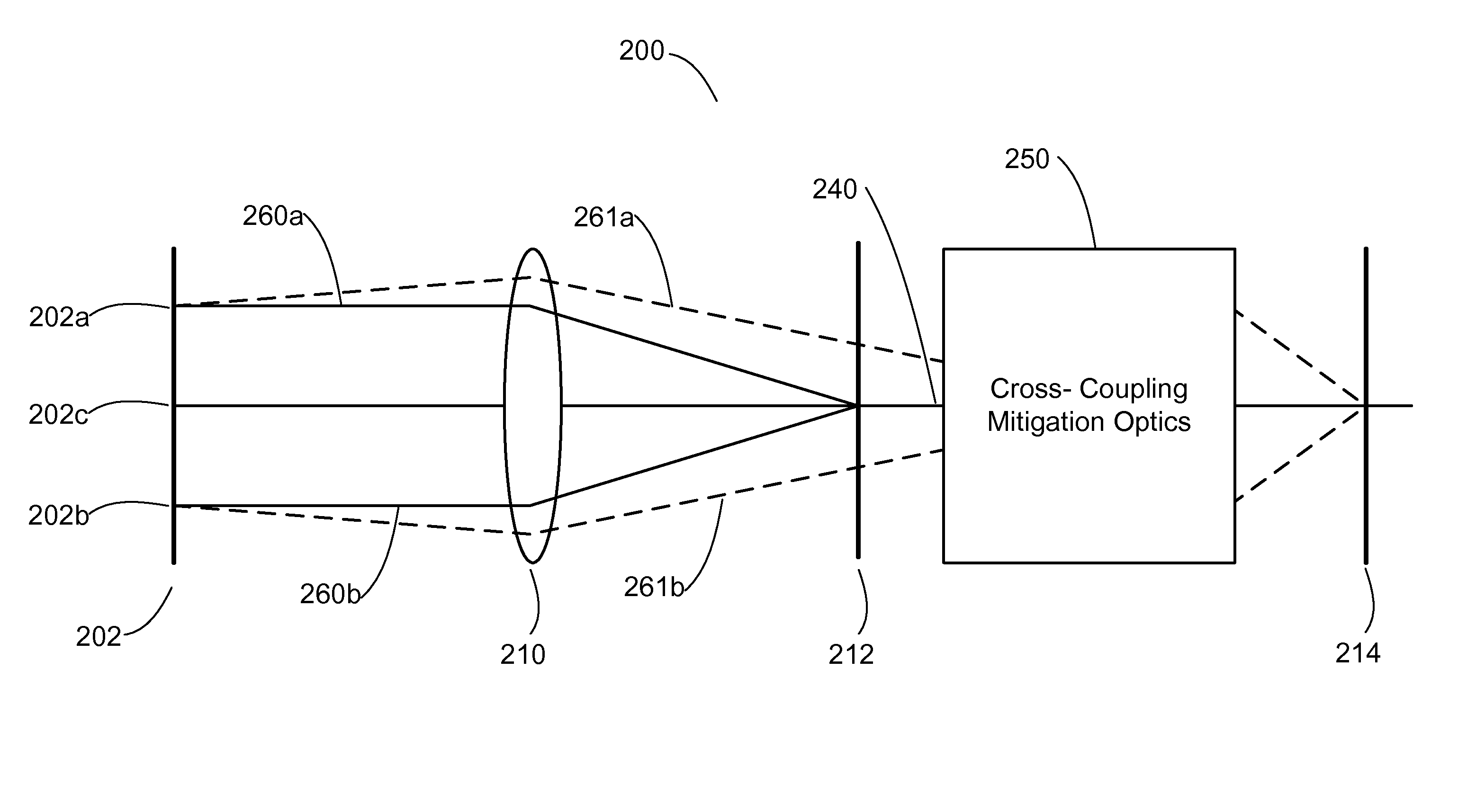
[0013]Embodiments described herein address mitigating the amount of unintended / undesired feedback from non-originated emitters. For example, two emitters in a WBC system sharing a common partially-reflective mirror, have the potential to cause feedback from one emitter to enter the second emitter. This undesirable feedback from a non-originated emitter reduces the efficiency of the system. . Other terms used in the art are cross-talk or cross-coupling, which these embodiments seek to mitigate or eliminate thereby increasing brightness and efficiency of a wavelength beam combining laser system.

[0014]The approaches and embodiments described herein may apply to one and two-dimensional beam combining systems ...


PUM


Abstract

A system and method for increasing efficiency and power output of a multi-wavelength beam combining system through providing a common output coupler to reflect feedback that stabilizes or individually seeds each emitter, and wherein the individual feedback is preserved by mitigating cross-coupling, wherein a multi-wavelength beam comprised of radiation having a plurality of wavelengths, high brightness and power.

Description

CROSS-REFERENCE TO RELATED APPLICATIONS[0001]This application claims priority as a continuation-in-part to the following U.S. Patent Applications, each of which is hereby incorporated by reference in its entirety: U.S. Ser. No. 13 / 218,251 filed Aug. 25, 2011, which claims priority to U.S. Ser. No. 61 / 376,900, filed Aug. 25, 2010, and also claims priority as a continuation-in-part to the following U.S. Non-provisional Patent Application, of which is hereby incorporated by reference in its entirety: U.S. Ser. No. 13 / 042,042 filed Mar. 7, 2011, which claims priority to each of the following U.S. Provisional Patent Applications, of which are hereby incorporated in their entirety: U.S. Ser. No. 61 / 310,777 filed Mar. 5, 2010; U.S. Ser. No. 61 / 310,781 filed Mar. 5, 2010, and U.S. Ser. No. 61 / 417,394 filed Nov. 26, 2010.BACKGROUND OF THE INVENTION[0002]1. Field of the Invention[0003]The present embodiments relate generally to laser systems and more particularly to wavelength beam combining ...

Claims


Application Information

Patent Timeline
IPC IPC(8): G02B27/10
CPCG02B19/0057G02B27/0905H01S5/4062H01S5/4087H01S5/4068G02B19/0014G02B27/1006H01S5/141G02B19/0028G02B5/18
Inventor CHANN, BIENHUANG, ROBINTAYEBATI, PARVIZ
Owner PANASONIC OF NORTH AMERICA
Why Eureka
Try Eureka