Durable pumps for abrasives

a technology of abrasives and pumps, which is applied in the direction of machines/engines, mechanical equipment, liquid fuel engines, etc., can solve the problems of high velocity flow of abrasive fluid around certain pump parts, cavitation and abrasion of pumps, and the impeller used in downhole centrifugal pumps experiences significant abrasion of downthrust washers, so as to prevent wear of thrust washers and flushes easily

Inactive Publication Date: 2013-08-15
SCHLUMBERGER TECH CORP
View PDF5 Cites 27 Cited by
  • Summary
  • Abstract
  • Description
  • Claims
  • Application Information

AI Technical Summary

Benefits of technology

[0003]Durable pumps for abrasives are provided. An example centrifugal pump stage for subsurface operation has a thrust washer located inside the circumference of an outboard clearance seal betwe en an impeller shroud and the diffuser. Relocation of the thrust washer allows the clearance seal to protect the thrust washer from abrasives. A centrifugal action of an outboard seal lip effects a separation of the particles from the fluid nearest the gap of the outboard seal and drives the particles away from the gap of the outboard seal. When an abrasive particle in the leakage flow does clear the outboard seal, the particle is readily flushed across the thrust washer by the leakage flow to the central fluid inlet to prevent wear of the thrust washer. In an implementation, the inside diameter of the thrust washer is approximately flush with the bore of a central fluid inlet of the pump stage. This summary section is not intended to give a full description of durable pumps for abrasives. A detailed description with example implementations follows.

Problems solved by technology

Such heterogeneous “liquid sandpaper” may result in cavitation and abrasion issues for pumps, especially if the solids cause deposits to build up against some surfaces of the pump or if the fluid itself has a slurry-like consistency.
The viscosity and other flow characteristics of a particular liquid mixture may result in high velocity flow of the abrasive fluid around certain pump parts.
Impellers used in downhole centrifugal pumps experience significant abrasion of the downthrust washers (hereinafter, “thrust washers”) when pumping fluids containing abrasives.

Method used


Image

  • Durable pumps for abrasives
  • Durable pumps for abrasives
  • Durable pumps for abrasives

Examples


Embodiment Construction

[0012]Overview

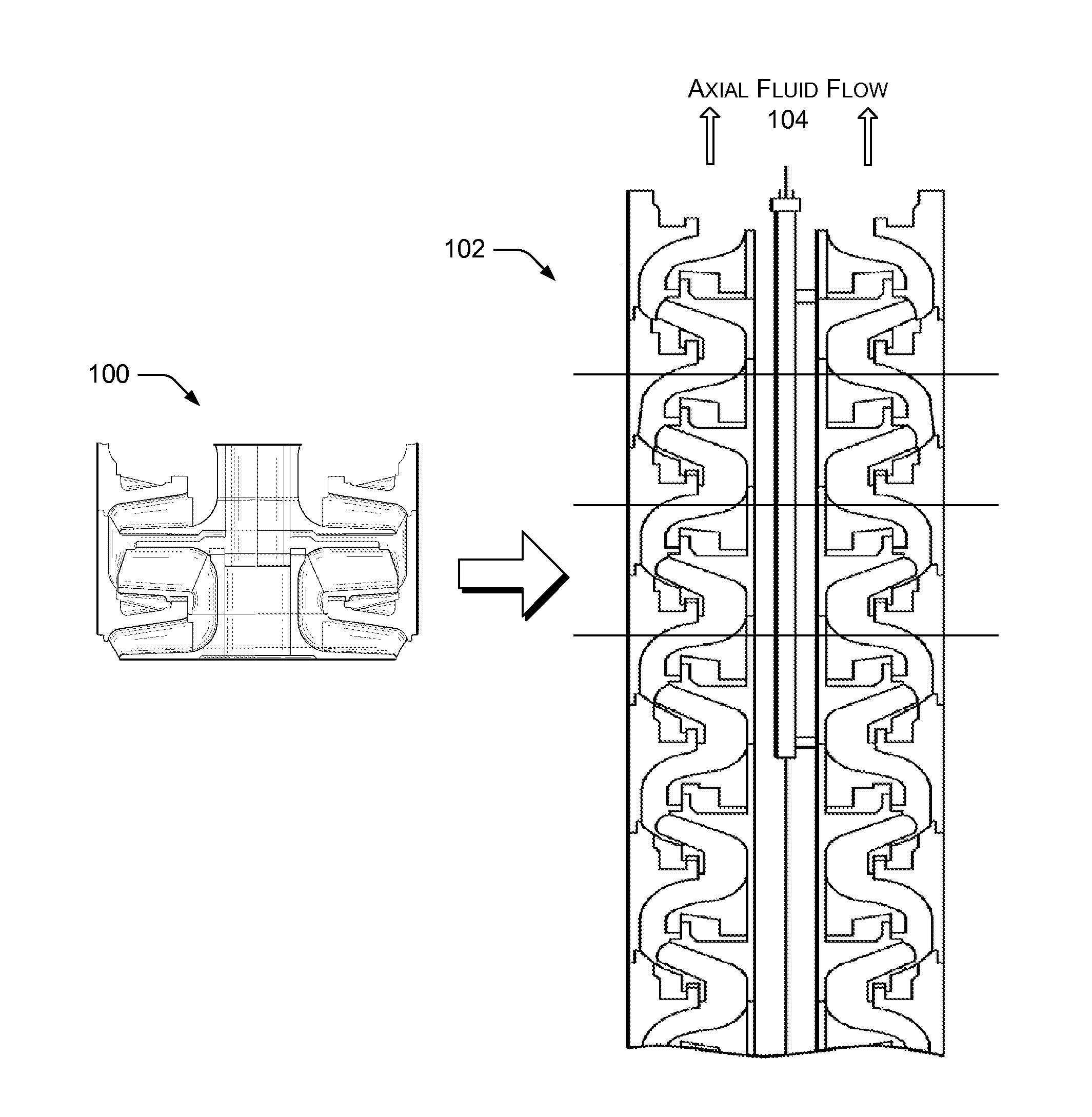
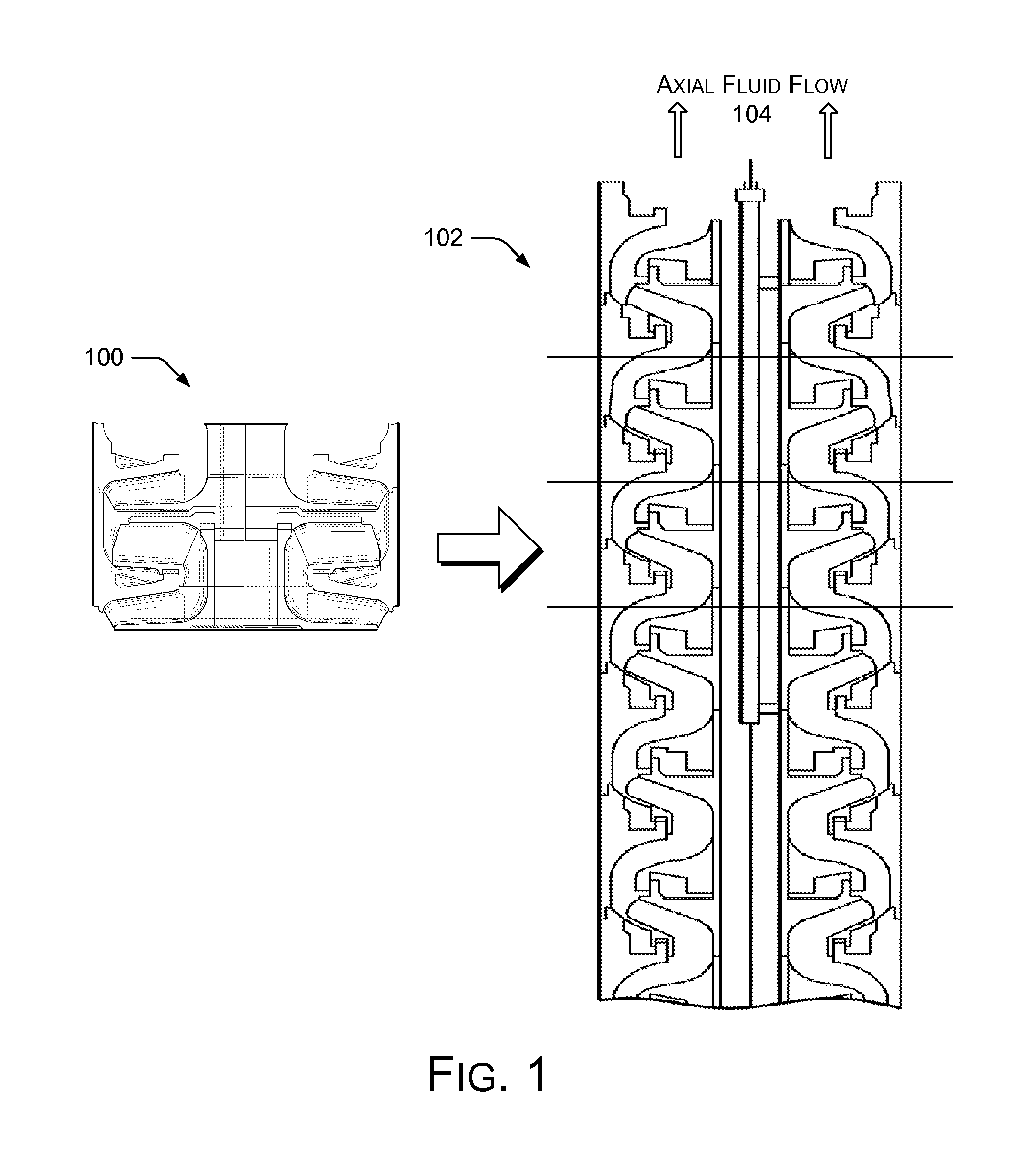
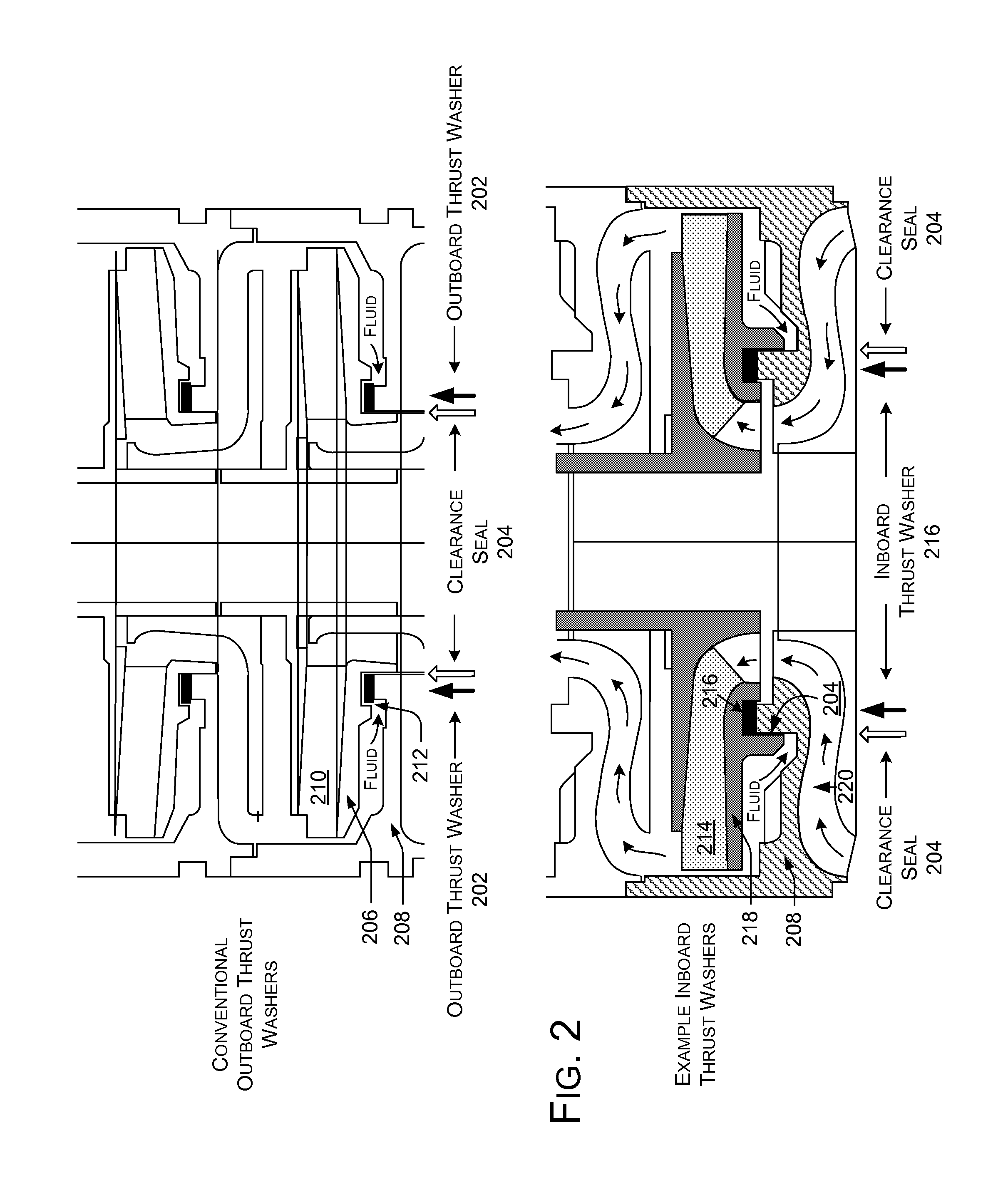
[0013]This disclosure describes durable pumps for abrasives. The described pumps provide higher wear and longer life than conventional designs, especially when pumping subsurface fluids containing some solids that tend to be abrasive when pumped, or when pumping slurries. FIG. 1 shows a cross-section of a centrifugal pump stage 100 of a multistage submersible pump stack 102. The multistage submersible pump stack 102 includes a number of the centrifugal pump stages 100 stacked together along their axial direction for ganged lift to generate axial fluid flow 104 in a subsurface environment. FIG. 2 shows example inboard thrust washers. FIGS. 3-6 show reduction of the diameter of example thrust washers, and associated benefits. FIGS. 7-8 show example methods of increasing the durability of pumps for abrasive fluids.

Example System Environment

[0014]Electric submersible pumps for abrasive fluids usually have at least one surface that is an impeller housing, or “shroud,” i.e.,...


PUM

PropertyMeasurementUnit
diameteraaaaaaaaaa
volumeaaaaaaaaaa
pressureaaaaaaaaaa

Abstract

Durable pumps for abrasives are provided. An example centrifugal pump stage for subsurface operation has a thrust washer located inside the circumference of an outboard clearance seal between an impeller shroud and the diffuser. Relocation of the thrust washer allows the clearance seal to protect the thrust washer from abrasives. A centrifugal action of an outboard seal lip effects a separation of the particles from the fluid nearest the gap of the outboard seal and drives the particles away from the gap of the outboard seal. When an abrasive particle in the leakage flow does clear the outboard seal, the particle is readily flushed across the thrust washer by the leakage flow to the central fluid inlet to prevent wear of the thrust washer. In an implementation, the inside diameter of the thrust washer is approximately flush with the bore of a central fluid inlet of the pump stage.

Description

RELATED APPLICATIONS[0001]This continuation patent application claims the benefit of priority to U.S. patent application Ser. No. 13 / 174,343 to Eslinger, filed Jun. 30, 2011 and entitled “Durable Pump for Abrasives,” which is incorporated herein by reference in its entirety, which in turn claims priority to U.S. Provisional Patent Application No. 61 / 365,695, filed Jul. 19, 2010, and entitled, “Centrifugal Pump with Increased Abrasion Resistance,” and to U.S. Provisional Patent No. 61 / 360,431, filed Jun. 30, 2010, and entitled, “Device and Means to Reduce Downthrust in a Multistage Centrifugal Pump,” both of which are incorporated herein by reference in their entirety.BACKGROUND[0002]Oilfields sometimes use electric submersible pumps staged in series to pump downhole fluids. A number of centrifugal pump stages can be stacked together along their axial direction for ganged lift in a subsurface environment. Such subsurface multistage pumps are frequently employed to move fluids consist...

Claims


Application Information

Patent Timeline
Patent Type & Authority Applications(United States)
IPC IPC(8): F04D1/06
CPCF04D7/04F04D13/10Y10T29/49243F04D1/06F04D29/167
Inventor ESLINGER, DAVID
Owner SCHLUMBERGER TECH CORP
Why Eureka
Try Eureka