Device for compartmental dilatation of blood vessels

a technology of compartmental dilatation and blood vessel, which is applied in the field of medical methods and devices, can solve the problems of limited cs expansion, severe trauma, fast and aggressive, etc., and achieve the effects of promoting plaque remodeling, promoting faster healing of diseased areas, and less trauma

Inactive Publication Date: 2013-08-15
TRIREME MEDICAL
View PDF2 Cites 57 Cited by
  • Summary
  • Abstract
  • Description
  • Claims
  • Application Information

AI Technical Summary

Benefits of technology

[0012]This invention discloses a device for angioplasty or dilatation of stenotic vessels and optionally for the delivery of active substance to the vessel wall. The balloon catheter disclosed here is designed to support a controlled and regulated plaque remodeling process promoting faster healing of the diseased area. This is achieved by modulation of the inflation characteristic resulting in less trauma to vessel wall during inflation.
[0013]This balloon catheter consists of a balloon catheter and a Constraining Structure (CS) located on the balloon portion of the catheter. The Constraining Structure (CS) serves to control and limit balloon inflation by modifying balloon topography and creating compartmental inflation where each inflation zone is independent of neighboring zones. This topography helps to promote plaque remodeling during inflation and allow for a controlled inflation with minimized trauma to vessel wall. The CS also inhibits transfer of shear forces to the lesion and vessel wall as the balloon inflates.
[0014]As the balloon inflates both balloon and CS structure increase in diameter however the CS maximal diameter is smaller than the balloon diameter. The balloon continues to inflate through the CS creating a topography of hills (pillows) and valleys (CS locations). The CS and balloon are capable of expanding due to inflation force applied by balloon dilation. The CS expansion is limited by its geometrical design. The CS is designed to limit balloon diameter, to eliminate transfer of tangential forces to vessel wall and to allow a plaque remodeling process that minimizes trauma and promotes faster healing.
[0015]A conventional balloon is compliant or semi-compliant and has a smooth even surface. During inflation the balloon will expand more easily in areas of less resistance, such as the less diseased areas (see Image 4A to 4C). In order to successfully open the lesion it is necessary to apply more pressure then when pressure is high enough the lesion will “give in” and open abruptly. This inflation process is fast and aggressive and may cause severe trauma. The device described in this invention is designed to allow a slow process of plaque remodeling where the plaque is able to flow and reshape itself due to the topography created by the CS. It creates a series of cushions where the CS is located at valleys between them (see FIG. 3). The CS channels between the cushions prevent high pressure buildup in the plaque and over expansion of the dilated vessel thus minimizing trauma caused to vessel walls during inflation. Thus the inflation process is controlled resulting in less trauma to the vessel and faster healing of the area.
[0016]The CS is situated over the deflated and folded balloon and attached to the catheter near the distal end of the balloon or near the proximal end of the balloon or preferably both. It also can be placed over the balloon without attachment. Upon balloon inflation the CS expands and allows the dilatation of the vessel by the balloon in a predetermined topography. During balloon dilation both the balloon and the CS structure increase in diameter while length of the device does not change. This further modulates the mechanics of inflation by minimizing the creation of axial tension forces on the vessel wall. Unlike conventional balloons where the length of the balloon will increase up to 10% during inflation the CS structure and balloon effective length do not change. When balloon length is maintained throughout the inflation process it allows predictability and more control of the inflation mechanism, and the healthy areas of the vessel are not exposed to inflation and tension forces exposing them to further damage.

Problems solved by technology

The CS expansion is limited by its geometrical design.
This inflation process is fast and aggressive and may cause severe trauma.

Method used


Image

  • Device for compartmental dilatation of blood vessels
  • Device for compartmental dilatation of blood vessels
  • Device for compartmental dilatation of blood vessels

Examples


Embodiment Construction

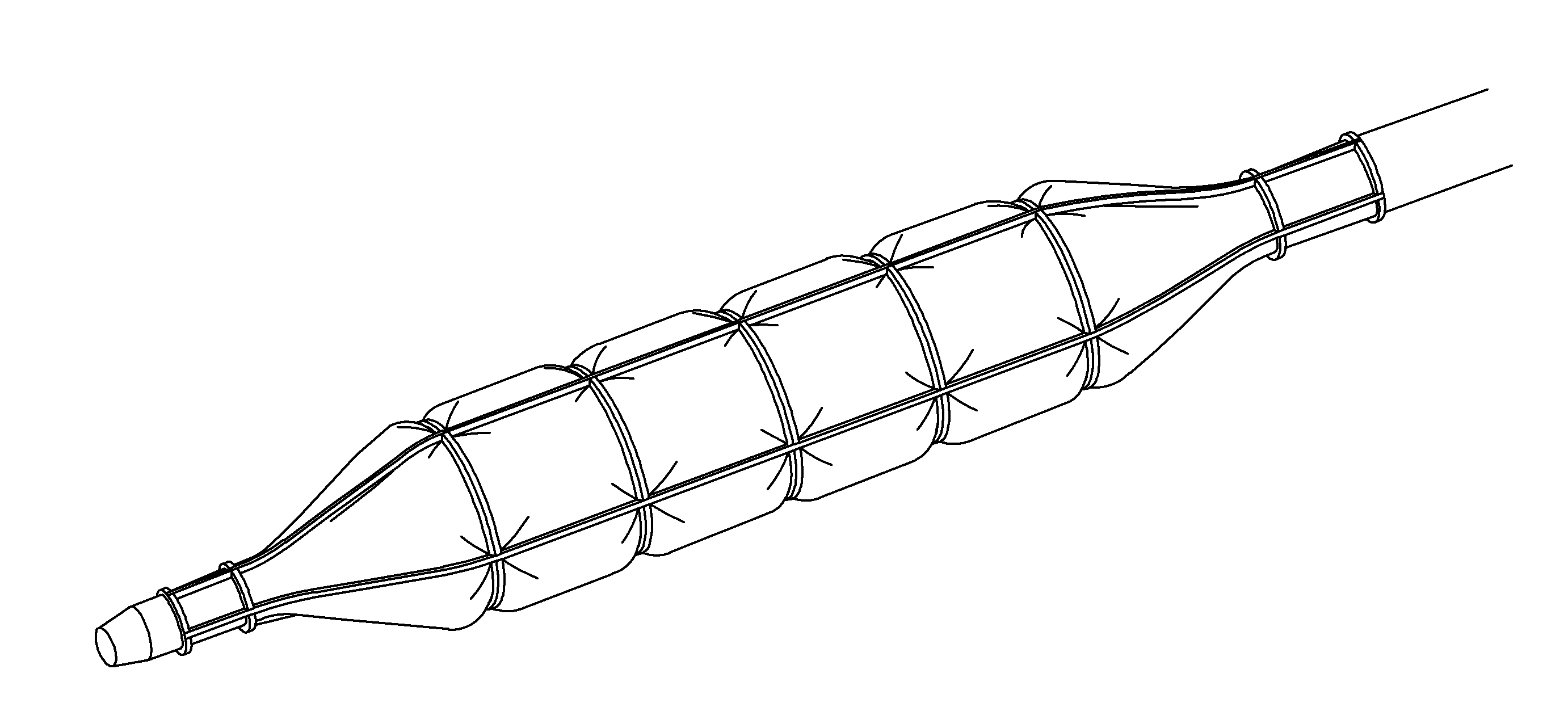
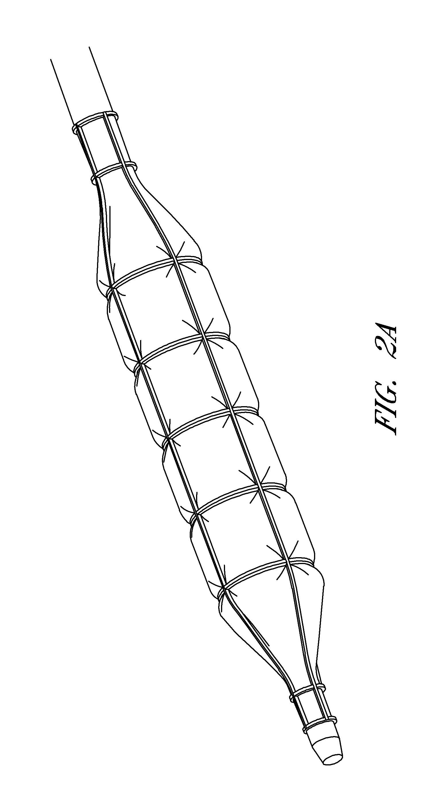
[0022]This invention discusses a device for treating of diseased, blocked, occluded or stenotic lumens in the body, typically blood vessels including both arteries and veins, and more typically coronary and peripheral arteries. This device dilates occluded vessels while causing minimal trauma to the lesion thus minimizing the risk of dissections, total occlusion, abrupt closure and restenosis, and promotes faster healing.

[0023]A Constraining Structure (CS) is placed over a balloon catheter where upon inflation both the balloon and the CS increase in diameter and during deflation the CS returns to its original dimensions. The CS can have multiple designs intended to expand to a diameter smaller than the maximal inflated diameter of the balloon. The CS can be connected to the balloon either on the distal side or the proximal side or both. It can also float over the balloon without firm attachment using simple covers since the CS can be designed to maintain its length during expansion ...


PUM


Abstract

A constraining structure for use with a balloon catheter includes multiple longitudinal struts and multiple expandable radial rings. The constraining structure can expand radially but may not expand substantially in the longitudinal direction. The constraining structure can have multiple compartments configured to expand independently of one another. Inflating the balloon catheter within the constraining structure can allow for dilation of the blood vessel in a predetermined topography.

Description

[0001]This application claims the benefit of U.S. Provisional Application No. 61 / 593,704, filed Feb. 1, 2012, the entirety of which is incorporated by reference herein.INCORPORATION BY REFERENCE[0002]All publications, patents, and patent applications mentioned in this specification are herein incorporated by reference to the same extent as if each individual publication, patent, or patent application was specifically and individually indicated to be incorporated by reference.BACKGROUND OF THE INVENTIONField of the Invention[0003]The present invention relates to the field of medical methods and devices, specifically to medical dilatation balloon catheters and devices intended to treat blood vessel obstructions and / or deliver active substance to body tissue.[0004]Angioplasty balloons are one of the most commonly used tools for treatment of narrowed and occluded blood vessels. These balloons are typically cylindrical when inflated and are manufactured in various dimensions (length and ...

Claims


Application Information

Patent Timeline
Patent Type & Authority Applications(United States)
IPC IPC(8): A61M25/10A61M29/02
CPCA61M25/104A61M2025/105A61M29/02A61M25/1002A61M2025/1084A61M25/10184A61M2025/1081
Inventor FELD, TANHUM
Owner TRIREME MEDICAL
Why Eureka
Try Eureka