Solid-state lamps with improved emission efficiency and photoluminescence wavelength conversion components therefor

Inactive Publication Date: 2013-08-22
INTEMATIX
View PDF28 Cites 21 Cited by
  • Summary
  • Abstract
  • Description
  • Claims
  • Application Information

AI Technical Summary

Benefits of technology

[0027]Some embodiments of the invention comprise a diffuser layer having particles of a light diffusive material (also referred to herein as “light scattering material”). One benefit of this arrangement is that by selecting an appropriate particle size and concentration per unit area of the light diffractive material, it is possible to make a device having an emission product color that is virtually uniform with emission angle over a ±60° range from the emission axis. Moreover the use of a light scattering material can substantially reduce the quantity of phosphor material required to generate a selected color of emitted light. In addition, the light diffusing material can significantly improve the white appearance of the light emitting device in its OFF state. The particles of a light diffractive material in the light diffusing layer are selected, for example, to have a size range that increases its probability of scattering blue light, which means that less of the external blue light passes through the light diffusing layer to excite the wavelength conversion layer. Therefore, the remote phosphor lighting apparatus will have more of a white appearance in an OFF state since the wavelength conversion component is emitting less yellow/red light. Preferably, to enhance the white appearance of the lighting device in an OFF state, the light diffractive material within the light diffusing layer is a “nano-particle” having an average particle size of less than about 150 nm. For light sources that emit lights having other colors, the nano-particle may correspond to other average sizes. For example, the light diffractive material within the light diffusing layer for an UV light source may have an average particle size of less than about 100 nm. Therefore, by appropriate selection of the average particle size of the light scattering material, it is possible to configure the light diffusing layer such that it scatters excitation light (e.g., blue light) more readily than other colors, namely green and red as emitted by the photoluminescence materials. For example, TiO2 particles with an average particle size of 100 nm to 150 nm are more than twice as likely to scatter blue light (450 nm to 480 nm) than they will scatter green light (510 nm to 550 nm) or red light (630 nm to 740 nm). As another example, TiO2 particles with an average particle size of 100 nm will scatter blue light nearly three times (2.9=0.97/0.33) more than it will scatter green or red light. For TiO2 particles with an average particle size of 200 nm these will scatter blue light over twice (2.3=1.6/0.7) as much as they will scatter green or red light. In accordance with some embodiments of the invention, the light diffractive particle size is preferably selected such that the particles will scatter blue light r

Problems solved by technology

Whilst LED-based lamps provide a significant improvement in efficiency compared with conventional incandescent lamps, LED-based lamps still generate a significant amount of heat that needs dissipating and are consequently heat sensitive.
This heat sensitivity causes LED lamp designs to require bulky thermal management structures to handle the amount of heat produced by the LED lamp.
This problem is most seen in high “wattage”

Method used


Image

  • Solid-state lamps with improved emission efficiency and photoluminescence wavelength conversion components therefor
  • Solid-state lamps with improved emission efficiency and photoluminescence wavelength conversion components therefor
  • Solid-state lamps with improved emission efficiency and photoluminescence wavelength conversion components therefor

Examples


Embodiment Construction

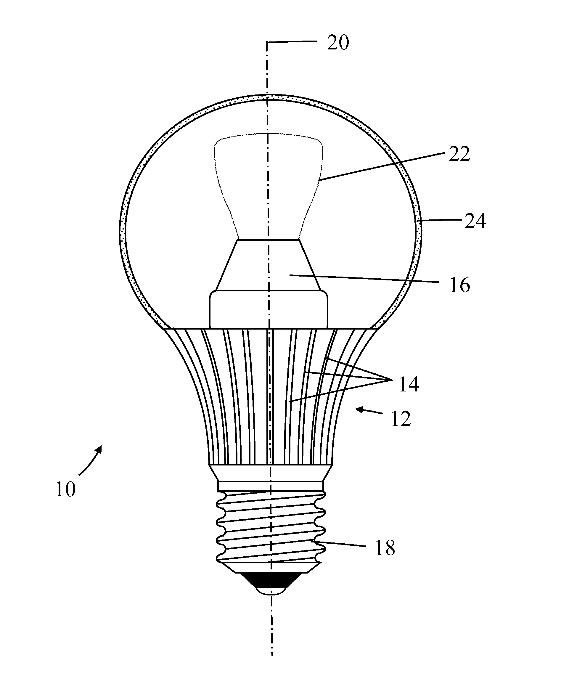
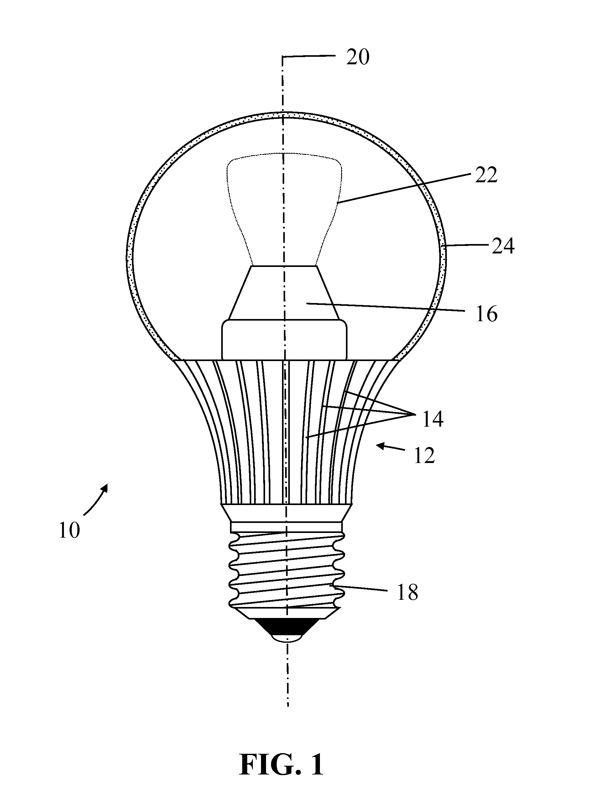
[0049]Lamps (light bulbs) are available in a number of forms, and are often standardly referenced by a combination of letters and numbers. The letter designation of a lamp typically refers to the particular shape of type of that lamp, such as General Service (A, mushroom), High Wattage General Service (PS—pear shaped), Decorative (B—candle, CA—twisted candle, BA—bent-tip candle, F—flame, P—fancy round, G—globe), Reflector (R), Parabolic Aluminized Reflector (PAR) and Multifaceted Reflector (MR). The number designation refers to the size of a lamp, often by indicating the diameter of a lamp in units of eighths of an inch. Thus, an A-19 type lamp refers to a general service lamp (bulb) whose shape is referred to by the letter “A” and has a maximum diameter two and three eights of an inch. As of the time of filing of this patent document, the most commonly used household “light bulb” is the lamp having the A-19 envelope, which in the United States is commonly sold with an Edison E26 sc...


PUM


Abstract

A solid-state lamp comprising: an array of solid-state excitation sources and a photoluminescence wavelength conversion component comprising a layer of photoluminescence material and a coupling optic. The layer of photoluminescence material is remote to the excitation sources and the coupling optic is disposed between the excitation sources and the layer of photoluminescence material. The ratio of the photoluminescence material surface area of the layer of the photoluminescence material to the excitation source surface area for the array of solid-state excitation sources is at least 3 to 1.

Description

CROSS-REFERENCES TO RELATED APPLICATIONS[0001]This application claims the benefit of U.S. Provisional Application No. 61 / 600,573, filed Feb. 17, 2012; U.S. Provisional Application No. 61 / 657,702, filed Jun. 8, 2012; and U.S. Provisional Application No. 61 / 666,695, filed Jun. 29, 2012 the content of each of which is hereby incorporated by reference in its entirety.BACKGROUND OF THE INVENTION[0002]1. Field of the Invention[0003]Embodiments of the invention relate to solid-state lamps with improved emission efficiency and photoluminescence wavelength conversion components for such lamps. In particular, although not exclusively, embodiments concern solid-state lamps with an improved radial emission characteristic. Embodiments of the invention further concern the design and manufacture of photoluminescence wavelength conversion components.[0004]2. Description of the Related Art[0005]White light generating LEDs, “white LEDs”, are a relatively recent innovation and offer the potential for ...

Claims


Application Information

Patent Timeline
IPC IPC(8): H05B33/12
CPCF21K9/56F21V3/00F21K9/135Y10T428/13H05B33/12F21V29/773F21Y2101/02F21K9/232F21K9/64F21Y2115/10
Inventor LI, YI-QUNYANG, HAITAOYUAN, XIANGLONGEDWARDS, CHARLES
Owner INTEMATIX
Why Eureka
Try Eureka