Position detecting device

a technology of positioning detection and detection device, which is applied in the direction of electrical control, instruments, machines/engines, etc., can solve the problem that the output circuit provided in the integrated circuit is likely to be damaged

Active Publication Date: 2013-08-22
DENSO CORP
View PDF1 Cites 4 Cited by
  • Summary
  • Abstract
  • Description
  • Claims
  • Application Information

AI Technical Summary

Benefits of technology

[0007]It is therefore an object to provide a position detecting device that can protect output circuits of plural integrated circuits when output terminals of the same are short-circuited.

Problems solved by technology

For this reason, when the output terminals of the two integrated circuits are short-circuited, and a larger current flows from one integrated circuit into the other integrated circuit than in a normal state, output circuits provided in the integrated circuits are likely to be damaged.

Method used


Image

  • Position detecting device
  • Position detecting device
  • Position detecting device

Examples


first embodiment

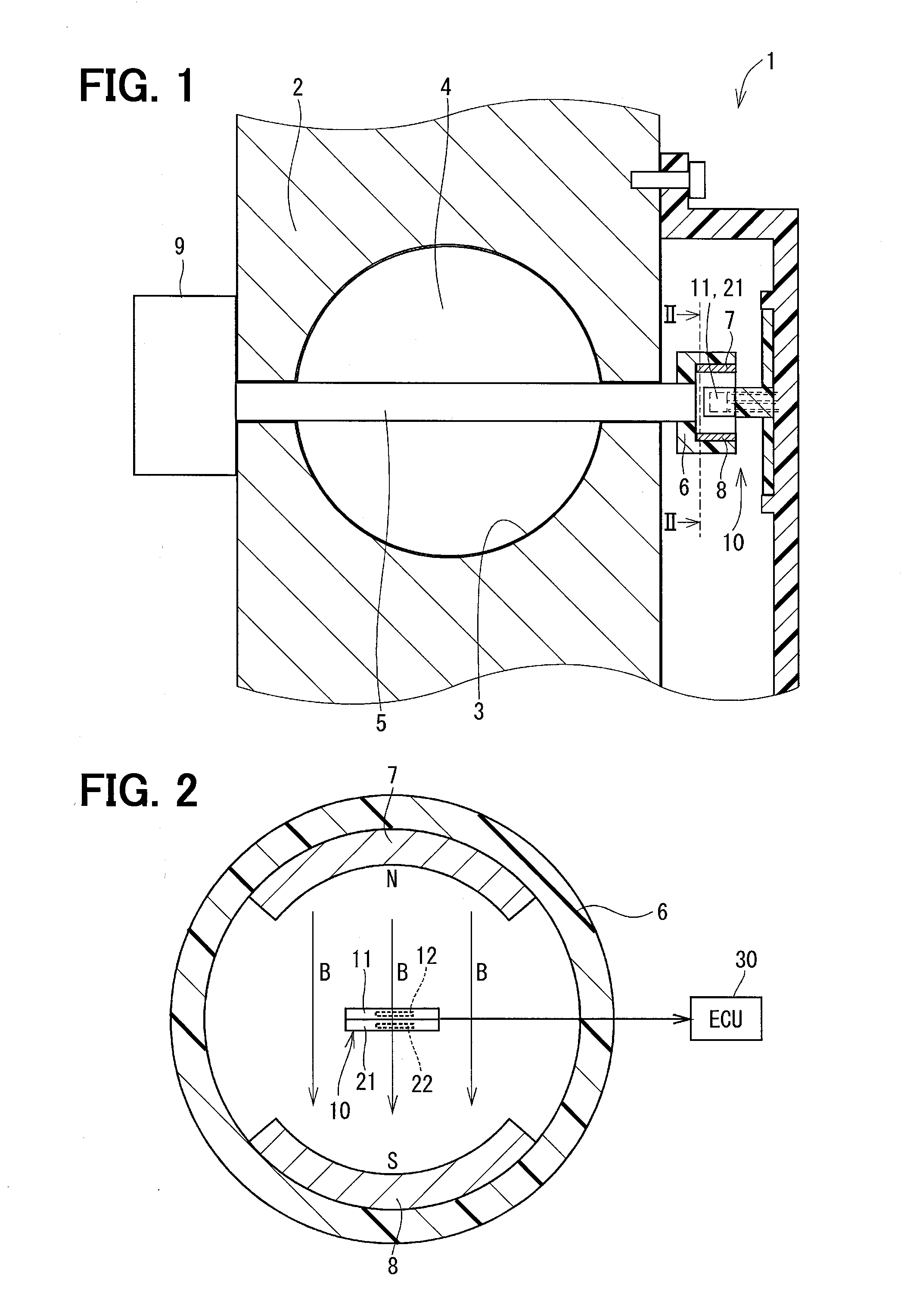
[0031]A position detecting device according to a first embodiment is illustrated in FIGS. 1 to 10 and designated by reference numeral 10. The position detecting device 10 is used in an electronic control throttle 1 that controls a quantity of air to be sucked into a cylinder of an internal combustion engine for a vehicle.

[0032]As shown in FIG. 1, a housing 2 of the electronic control throttle 1 has an intake passage 3 that introduces air into the internal combustion engine. A throttle valve 4 formed into a substantially disc shape is disposed within the intake passage 3. The throttle valve 4 is integrated with a valve shaft 5. Both ends of the valve shaft 5 are rotatably supported on the housing 2. With this configuration, the throttle valve 4 can be rotated about the valve shaft 5 as a rotating shaft.

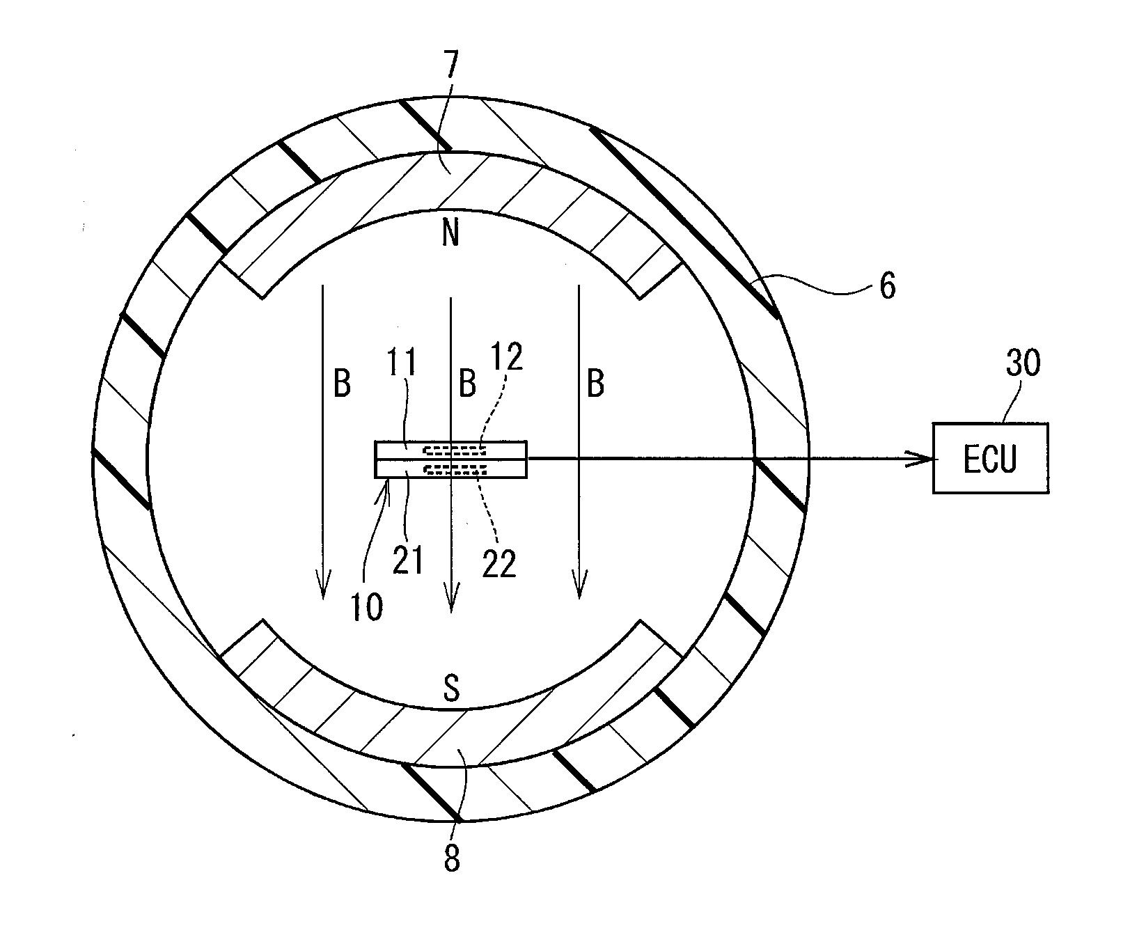
[0033]One end of the valve shaft 5 is fixed with a cylindrical yoke 6, and two permanent magnets 7 and 8 are disposed on a radial inner side of the yoke 6 to face each other. The perma...

second embodiment

[0088]A position detecting device according to a second embodiment is illustrated in FIGS. 11 to 16. In the second embodiment, the position detecting device 10 is configured to have a characteristic of a signal output to the ECU 30 in the normal state as shown in FIG. 11.

[0089]In the second embodiment, in the normal state, the ECU 30 uses the voltage signal V2 of the negative characteristic output from the second integrated circuit 21 as the control signal for driving the motor 9. Also, the ECU 30 uses the voltage signal V1 of the positive characteristic output from first integrated circuit 11 as a monitor signal for monitoring operation states of the two integrated circuits 11 and 21. That is, the integrated circuit for control operation and the integrated circuit for monitor operation in the first embodiment are replaced with each other.

[0090]For this reason, in the second embodiment, the factory write bit is set to “1” and stored in both of the storage units 64 and 94 of the two ...

third embodiment

[0113]A position detecting device according to a third embodiment is illustrated in FIGS. 17 and 18.

[0114]A characteristic of a signal output by the position detecting device of the third embodiment to the ECU 30 in the normal state is illustrated in FIG. 17.

[0115]In the third embodiment, in the normal state, the ECU 30 uses a voltage signal V5 of the positive characteristic output from one integrated circuit as a control signal for driving the motor 9. Therefore, the factory write bit is stored as “0” in both of the storage units 64 and 94 of the two integrated circuits 11 and 21.

[0116]Also, the ECU 30 uses a voltage signal V6 output from the other integrated circuit as a monitoring signal for monitoring the operation states of the two integrated circuits 11 and 21.

[0117]The voltage signal V6 output from the integrated circuit for monitor operation is large in a change of an area ZS smaller in the opening angle of the throttle valve 4. As a result, the ECU 30 can precisely monitor ...


PUM


Abstract

A position detecting device has an output circuit, which controls voltages of signal lines connecting a power supply and a ground by a power side transistor and a ground side transistor. An output signal line connects a connection point of the signal lines and an output terminal. A first comparator circuit outputs a signal “1” when a current flowing in the line between the power supply and the connection point is larger than a normal current flowing into the ground from the power supply in a normal state. A second comparator circuit outputs a signal “1” when a current flowing in the line between the connection point and the ground is larger than the normal current. When the signal “1” is output from the first comparator circuit or the second comparator circuit, a cutoff circuit turns off a switch disposed in the output signal line.

Description

CROSS REFERENCE TO RELATED APPLICATION[0001]This application is based on and incorporates herein by reference Japanese patent application No. 2012-032553 filed on Feb. 17, 2012.TECHNICAL FIELD[0002]The present disclosure relates to a position detecting device that detects a rotation angle or a stroke amount of an object to be detected.BACKGROUND[0003]Many conventional position detecting devices detect a rotation angle of a throttle valve, which controls a quantity of air sucked into a cylinder of an internal combustion engine for a vehicle. The position detecting device has a magnetic detection element for detecting a magnetism developed by a magnet disposed in the throttle valve and outputs the detected magnetism value to an electronic control unit (ECU) for the vehicle. The ECU supplies a current to a motor for rotating the throttle valve so that the rotation angle of the throttle valve, which is calculated on the basis of a signal output from the position detecting device matches...

Claims


Application Information

Patent Timeline
Patent Type & Authority Applications(United States)
IPC IPC(8): G01B7/30
CPCG01B7/30F02D41/0002G01D3/08G01D5/145Y02T10/40F02D11/107F02D2041/227F02D2200/0404F02D41/221
Inventor SHINTANI, HIROYUKIKUBOTA, TAKAMITSUKONO, YOSHIYUKI
Owner DENSO CORP
Why Eureka
Try Eureka