Method for Operating a Coil and a Monitoring Module

a monitoring module and coil technology, applied in the field of coil operation, can solve the problems of no damage to the tomography system nor the patient, no longer acceptable patient noise, and known loud noise, and achieve the effect of reducing the overshoot characteristics

Active Publication Date: 2013-08-22
SIEMENS HEALTHCARE GMBH
View PDF3 Cites 11 Cited by
  • Summary
  • Abstract
  • Description
  • Claims
  • Application Information

AI Technical Summary

Benefits of technology

[0026]Alternatively, the execution of the electrical resonant circuit model or the monitoring module, as applicable, may be implemented as a freely programmable logic circuit (e.g., a field-programmable gate array (FPGA)). This enables particularly rapid signal processing.
[0029]The mechanical resonance response may be modeled not exactly using the electrical resonant circuit model, but instead, for example, a central frequency that is somewhat greater than the measured mechanical resonance frequency may be assigned to the resonant circuit model. This is advantageous, for example, if the coil is a gradient coil, because it is thereby possible to achieve a better coverage of different tolerance states that may arise due to changes in the gradient coil mounting.
[0031]It is advantageous if the electrical resonant circuit model is based on a digital infinite impulse response (IIR) bandpass filter. The creation of digital IIR bandpass filters is well understood, and rapid signal processing may be provided. A prerequisite for digital filters is discrete numeric values as the input signals. Each individual numeric value undergoes digital processing. The numeric values are realized using logic modules or in the form of a software program.
[0045]In another embodiment, the act to check for resonances is carried out in parallel with a digital-to-analog conversion of the signal for the current. In a magnetic resonance tomography system, the controller provides a current set value in digital form. This under-goes a digital-to-analog conversion, is amplified and is then fed into the coil. The check for resonance is advantageously carried out at the same time as the digital-to-analog conversion, so that there is no loss of time. If this establishes that the chosen gradient pulse sequence would lead to damaging resonances, then the feeding of the current into the gradient coils is suppressed.
[0047]In one development, the blocking of the current flow is carried out by the actuation of an amplifier. By this, the emission may be suppressed without the need for an additional switch.
[0050]In one development, the absolute value of the output signal from the digital resonant circuit model is formed, or the individual discrete signal values are squared, before the comparison with the threshold value. This signal processing reduces the overshoot characteristics. As an alternative to this or in a further form of embodiment, as applicable, the output signal from the digital resonant circuit model may also be passed through a moving average filter before the output signal is compared with the threshold value. This again avoids overshoots.

Problems solved by technology

Displacements of the gradient coils lead to known loud noises during magnetic resonance tomography.
While these noises are perceived as disturbing, the noises are, however, neither damaging for the tomography system nor for the patient.
Here, the noise is so loud that the noise is no longer acceptable for the patient.
In addition, the mechanical vibrations have an effect on the gradient coil supply cables and on the gradient coil connections.
As a result, for example, the screw connections on the gradient coils may become high resistance and, during longer periods of operation, heat up.
Frictional heat may also result in warming.
In an extreme case, the warming may become so intense that the warming leads to damage to the device.
Strong mechanical vibrations, such as arise in the case of a resonance, may also lead to a breakage in the coils or in the supply cables or in the devices for fixing the gradient coils.
The problem of mechanical resonance in the gradient coils arises, for example, in the case of very rapid magnetic resonance tomography imaging technology (e.g., with echo planar imaging (EPI)).
Apart from the mechanical effects of a resonant vibration of the gradient coil system, already described, in the case of echo planar imaging resonance, the resonance may also lead to artifacts in the image in the form of EPI ghosting (e.g., ghost image formation).
Resonance may cause warming, resulting in an increased rate of helium evaporation.
In the extreme situation, the increased rate of evaporation may lead to magnetic quenching if the helium supply falls below the critical quantity.
The software then prevents the possibility of executing gradient pulse sequences that contain frequencies within the forbidden frequency bands.
A disadvantage of this approach is that the approach makes all sequences that contain frequencies within the forbidden frequency bands unexecutable.
The filing of forbidden frequency bands restricts the imaging options unnecessarily.
If the user circumvents the frequency band bans, for example, because the amplitude has incorrectly been estimated to be adequately low, this may still lead to resonance excitation and, as a consequence, to damage to the gradient coil system.

Method used


Image

  • Method for Operating a Coil and a Monitoring Module
  • Method for Operating a Coil and a Monitoring Module
  • Method for Operating a Coil and a Monitoring Module

Examples


Embodiment Construction

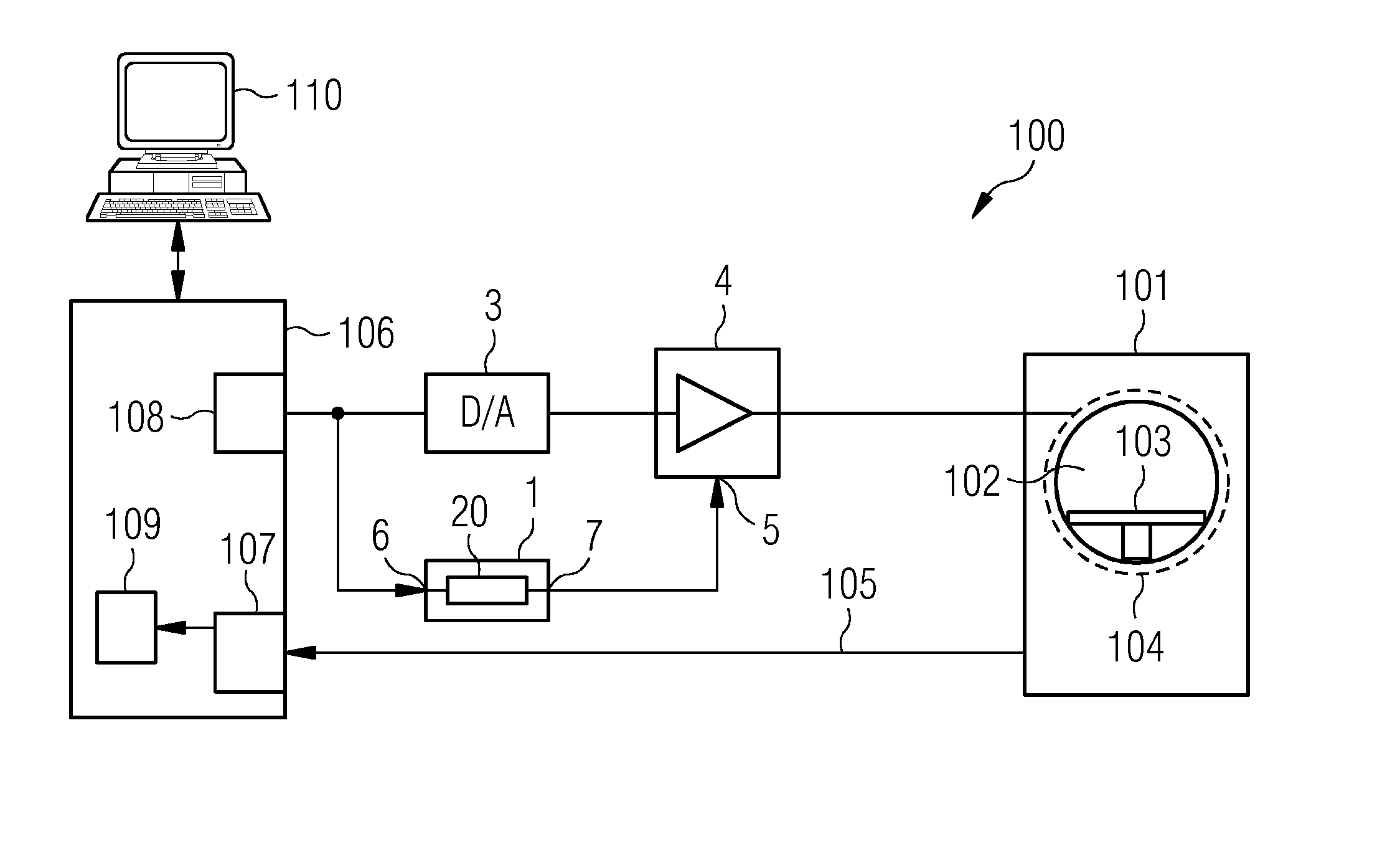
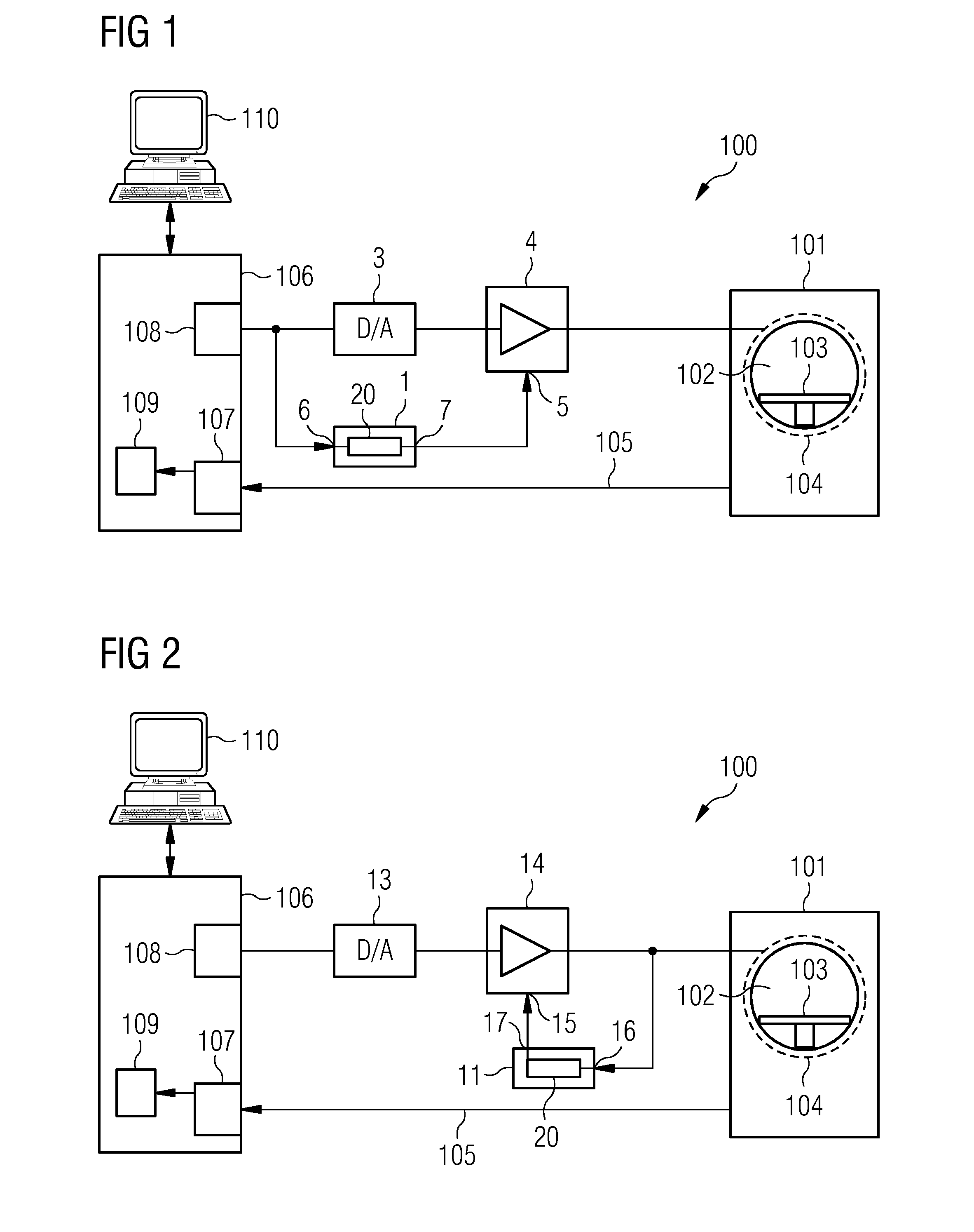
[0057]FIG. 1 shows a schematic block diagram of one embodiment of a magnetic resonance tomography system 100. A monitoring module 1 is used in the magnetic resonance tomography system 100. Even though the following description refers to a magnetic resonance tomography system, the invention is not restricted to this application situation.

[0058]A central part of the magnetic resonance tomography system 100 is a normal scanner 101, in which a patient or experimentee (not shown) may be positioned for an investigation on a table 103 in a measurement space 102 (e.g., a “patient tunnel”). This representation is to be understood as not restrictive. The method and the monitoring module may be used in magnetic resonance tomography systems of the open type, in which the investigation space is of a more open construction.

[0059]The scanner 101 has a basic magnetic field system for the purpose of applying, to the measurement space 102, a basic magnetic field together with a gradient coil system 1...


PUM


Abstract

A method for operating a coil, through which a varying current flows, is provided. Mechanical resonance responses of the coil are recorded and are modeled by an electrical resonant circuit model. A check is made as to whether a varying current that is to be sent through the coil evokes a resonant response in the electrical resonant circuit model. The current flow through the coil is blocked if the resonant response exceeds a predefined limit value.

Description

[0001]This application claims the benefit of DE 10 2012 202 416.6, filed on Feb. 16, 2012, which is hereby incorporated by reference.BACKGROUND[0002]The present embodiments relate to a method for operating a coil, through which a varying current flows.[0003]An electric current always produces a magnetic field. In an electric coil, this magnetic field is especially marked. If another external magnetic field is present, an interaction results, and an attraction or repulsion of the coil results. This physical effect is well known and is consciously exploited in many applications. Coils are also used in various forms and with various functions in a magnetic resonance tomography system.[0004]Magnetic resonance tomography (e.g., nuclear spin tomography) is a technique that has become widespread for the acquisition of images of the interiors of the bodies of living objects under investigation. In order to obtain an image using this method (e.g., a magnetic resonance record of an object und...

Claims


Application Information

Patent Timeline
Patent Type & Authority Applications(United States)
IPC IPC(8): G01R33/54
CPCG01R33/54G01R33/3854
Inventor DIETZ, PETERPIRKL, GEORGSPECKNER, THORSTEN
Owner SIEMENS HEALTHCARE GMBH
Why Eureka
Try Eureka