Wide band semi-specular mirror film incorporating nanovoided polymeric layer

Active Publication Date: 2013-08-22
3M INNOVATIVE PROPERTIES CO
View PDF7 Cites 35 Cited by
  • Summary
  • Abstract
  • Description
  • Claims
  • Application Information

AI Technical Summary

Benefits of technology

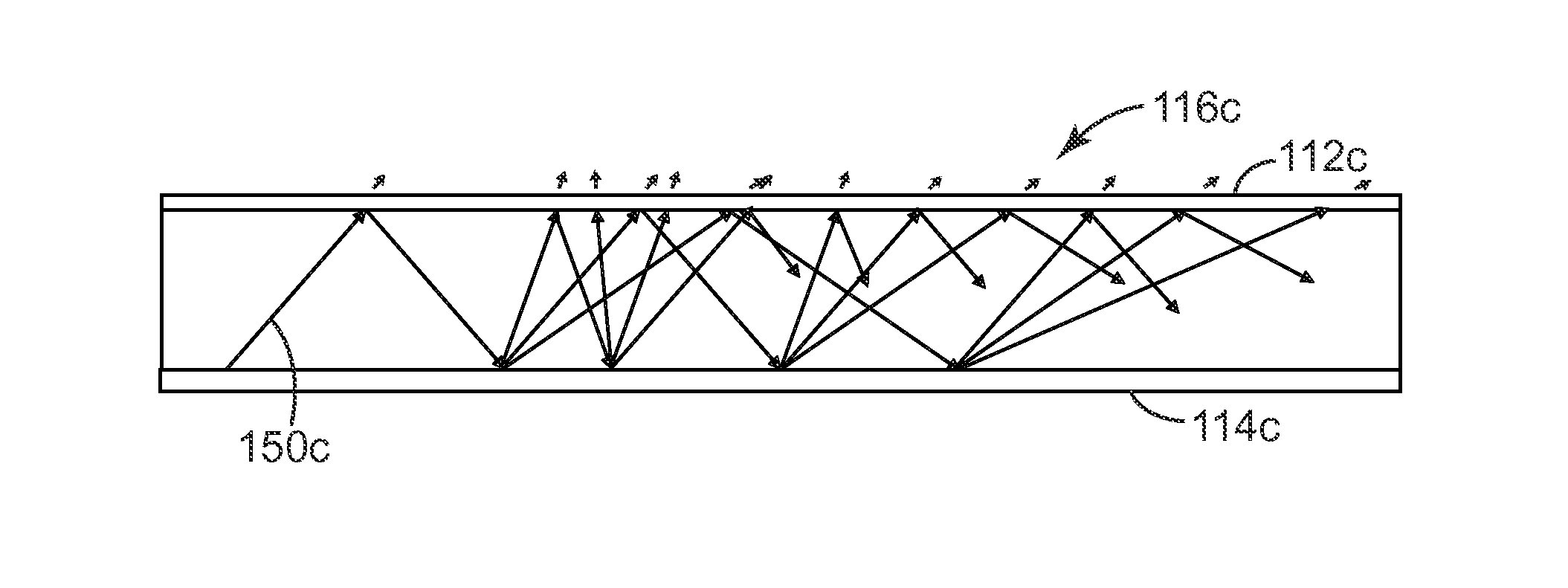
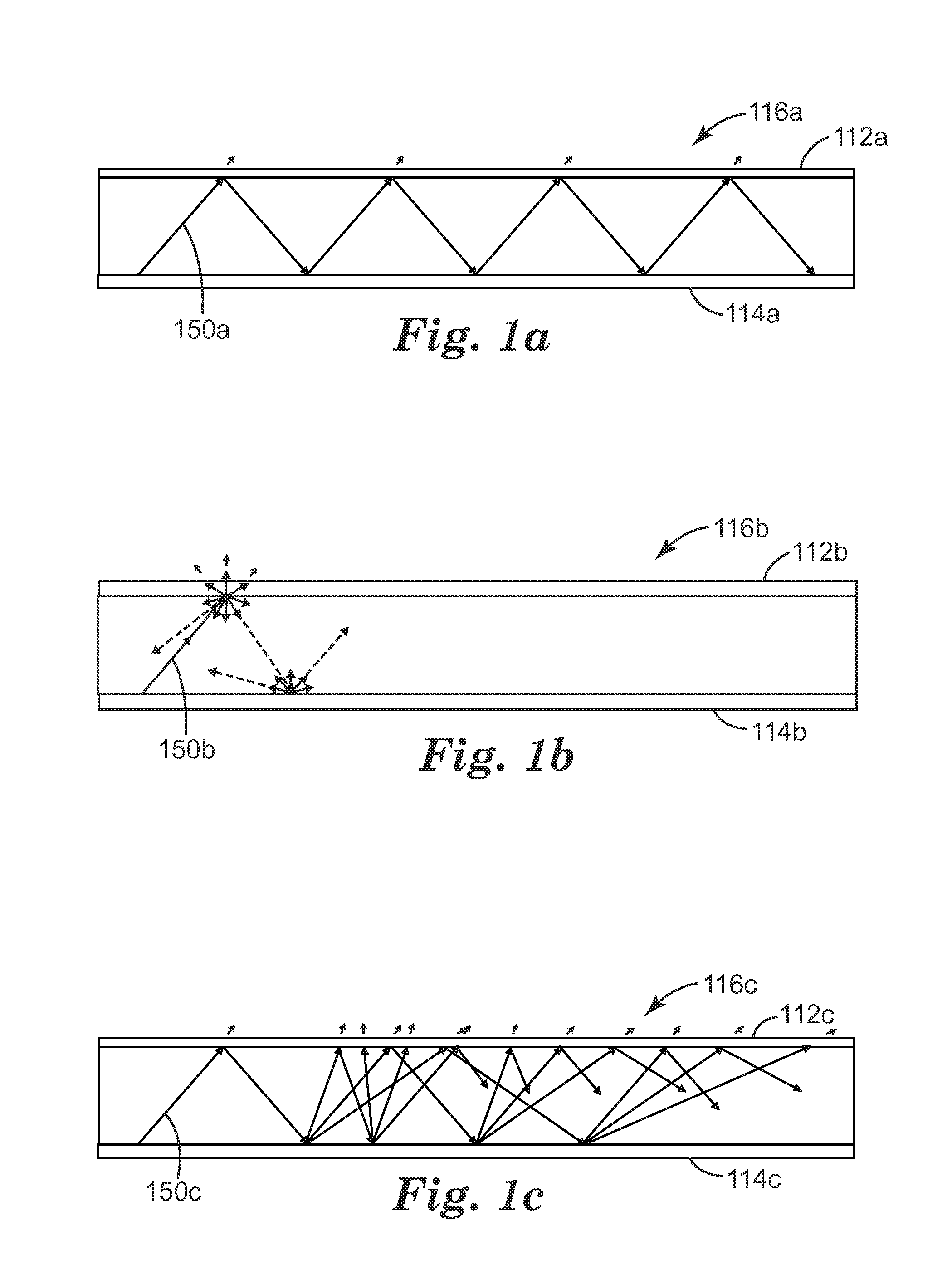
[0013]We have found that semi-specular reflective mirror films can be used to provide highly efficient light guides that may evenly distribute light across a backlight area or display area even in cases where the light source is located at one end or edge of the device, e.g., in the case of a backlight or other extended-area light source that uses one or more edge-mounted LED light sources. The semi-specular mirror films described further herein may find utility in a variety of applications, such as energy efficient display devices that use fewer and brighter LED sources, and/or direct-lit fluorescent or LED l

Problems solved by technology

However, no angular mixing occurs in the cavity, since there is no mechanism to convert light propagating at a given incidence angle to other incidence angles.
Certain design challenges arise when combining a diffusing layer with an MOF.
This effect, combined with the fact that the reflection band of the MOF shifts to shorter wavelengths as the propagation angle increases, and the fact that the spectral width of the reflection band is limited by th

Method used


Image

  • Wide band semi-specular mirror film incorporating nanovoided polymeric layer
  • Wide band semi-specular mirror film incorporating nanovoided polymeric layer
  • Wide band semi-specular mirror film incorporating nanovoided polymeric layer

Examples


example 1

[0196]50 g of methanol and 15 g of TS 530 were charged to a 400 ml plastic laboratory beaker equipped with an air driven 3-blade paddle stirrer. The TS 530 powder was added to the stirred methanol in small portions to aid in dispersion. The agitator was at first run slowly until the particles were wetted by the solvent. The mixture became very viscous and about 50 g of additional methanol was added slowly. It was necessary to use a wooden spatula to repeatedly push the particles that adhered to the side of the flask back into the mixture. Once all the particles were immersed in the solvent, the agitation rate was increased and an additional small amount of methanol was added. The solids content of the final mixture was found to be 14%. During storage, the particle mixture was placed on a standard laboratory shaker set at low speed to ensure the particles did not settle out of the mixture. Using the same mixing apparatus, 30 g of 10% FC 2145 in methanol was charged to a 200 ml plasti...

examples 2-6

[0198]Examples 2-6 were prepared in the same manner as Example 1 but the solvent and resins were changed as shown in Table 1.

examples 7-8

[0199]The coating mixtures used to prepare the specimens of Examples 7 and 8 were prepared from mixtures of PVA-235 and the fumed silicon oxide dispersion Cab-O-Sperse PG002™. Poly Cup 172™ (PC 172) was used as the crosslinker in the formulation. PC 172 is a polyamide-epichlorohydrin polymer available as a 12% solids solution in water from Hercules Corp. of Newark, Del. 100 g of deionized water, 0.5 ml of ammonium hydroxide (30 wt %) and 2.0 g of PC 172 (2.5 wt % based on PVA content) were added to an 800 ml plastic beaker and mixed thoroughly with a stirring rod. 300 g of Cab-O-Sperse PG002 fumed silicon oxide dispersion (20 wt % in water) and 2.0 g of surfactant Tergitol Min-Foam 1X™ (Dow Chemical of Midland, Mich.) (10 wt % in water) were then added. Once these were well mixed, 138.8 g of 7.2 wt % PVA 235 solution and another 160 g of deionized water were added to the mixture followed by additional mixing with a stirring rod. The coating mixture was transferred to a 1 L, 1-neck r...


PUM


Abstract

Low loss, high reflectivity wide band mirror films provide a desired mix of specular reflection and diffuse reflection or scattering to provide semi-specular reflectivity. The mirror films generally include both a specularly reflective multilayer optical film (MOF) having a wide reflection band, and a scattering layer. In some cases a low refractive index TIR layer is sandwiched between the MOF and the scattering layer. In other cases the scattering layer contacts the MOF directly. In embodiments that include the TIR layer, the TIR layer preferably has a nanovoided morphology and includes a plurality of particles and a polymer binder. In embodiments wherein the scattering layer contacts the MOF directly, the scattering layer preferably also has a nanovoided morphology and includes a plurality of particles and a polymer binder.

Description

FIELD OF THE INVENTION[0001]This invention relates generally to optical films whose reflection and transmission characteristics are determined in large part by constructive and destructive interference of light reflected from interfaces between microlayers within the film, with particular application to such films that have very high reflectivity and low transmission of light over an extended wavelength range. The invention also relates to associated articles, systems, and methods.BACKGROUND[0002]Multilayer optical films are known. Such films typically incorporate a large number of very thin layers of different light transmissive materials, the layers being referred to as microlayers because they are thin enough so that the reflection and transmission characteristics of the optical film are determined in large part by constructive and destructive interference of light reflected from the layer interfaces. Depending on the amount of birefringence (if any) exhibited by the individual m...

Claims


Application Information

Patent Timeline
IPC IPC(8): G02B5/28
CPCG02B5/0242G02B5/285G02B5/0841G02B5/0247G02B5/02G02B5/08
Inventor COGGIO, WILLIAM D.BLACK, WILLIAM B.WEBER, MICHAEL F.TAI, HUIWEN
Owner 3M INNOVATIVE PROPERTIES CO
Why Eureka
Try Eureka