Control arrangement

a control arrangement and control technology, applied in the field of control arrangement, can solve the problems of cumbersome provisioning, difficult to provide distributed synchronization units, and large amount of cabling, and achieve the effect of reducing inrush current or repercussions

Active Publication Date: 2013-08-22
HITACHI ENERGY SWITZERLAND AG
View PDF2 Cites 7 Cited by
  • Summary
  • Abstract
  • Description
  • Claims
  • Application Information

AI Technical Summary

Benefits of technology

[0007]While the control arrangement described above can reduce inrush currents or repercussions to non-critical values, it has nevertheless some drawbacks. It requires for each synchronization device considerable amount of cabling. Each synchronization device needs to be fed with the same voltage reference, i.e. a bus bar voltage. The more circuit breakers that are present in the circuit breaker station or substation, the more cabling is required, and it will be cumbersome to provide each of the synchronization devices with the correct signals.
[0009]Still further, in circuit breaker stations or substations using distributed units to operate the breakers using a process bus such as e.g. IEC61850-9-2 or other Ethernet based field bus such as EtherCat, it would be difficult to provide the distributed synchronization units with the synchronization function (point-of-wave switching function) as the synchronization function would require voltages and currents to be sent downstream the process bus to the distributed synchronization devices. This may restrict the bus structures possible to use and complicates the engineering efforts.
[0012]It is a further object of the invention to provide such a control arrangement, which relaxes the requirements on the distributed units that operate the circuit breakers.
[0013]It is yet a further object of the invention to provide such a control arrangement, which is robust, reliable, and of low cost.
[0017]The circuit breaker operating units can thus be cheap and simple and no complex cabling is required; for each unit only one connection to the central control system and one connection to the circuit breaker are required. Preferably, the central control system and the circuit breaker operating units communicate via a process bus such as e.g. IEC61850 or other Ethernet based field bus such as EtherCat.

Problems solved by technology

While the control arrangement described above can reduce inrush currents or repercussions to non-critical values, it has nevertheless some drawbacks.
It requires for each synchronization device considerable amount of cabling.
The more circuit breakers that are present in the circuit breaker station or substation, the more cabling is required, and it will be cumbersome to provide each of the synchronization devices with the correct signals.
Further, in circuit breaker stations or substations with complex bus structures, complex selection arrangements with relays may be required to select correct bus voltage for the synchronization.
Still further, in circuit breaker stations or substations using distributed units to operate the breakers using a process bus such as e.g. IEC61850-9-2 or other Ethernet based field bus such as EtherCat, it would be difficult to provide the distributed synchronization units with the synchronization function (point-of-wave switching function) as the synchronization function would require voltages and currents to be sent downstream the process bus to the distributed synchronization devices.
This may restrict the bus structures possible to use and complicates the engineering efforts.

Method used


Image

  • Control arrangement
  • Control arrangement
  • Control arrangement

Examples


Embodiment Construction

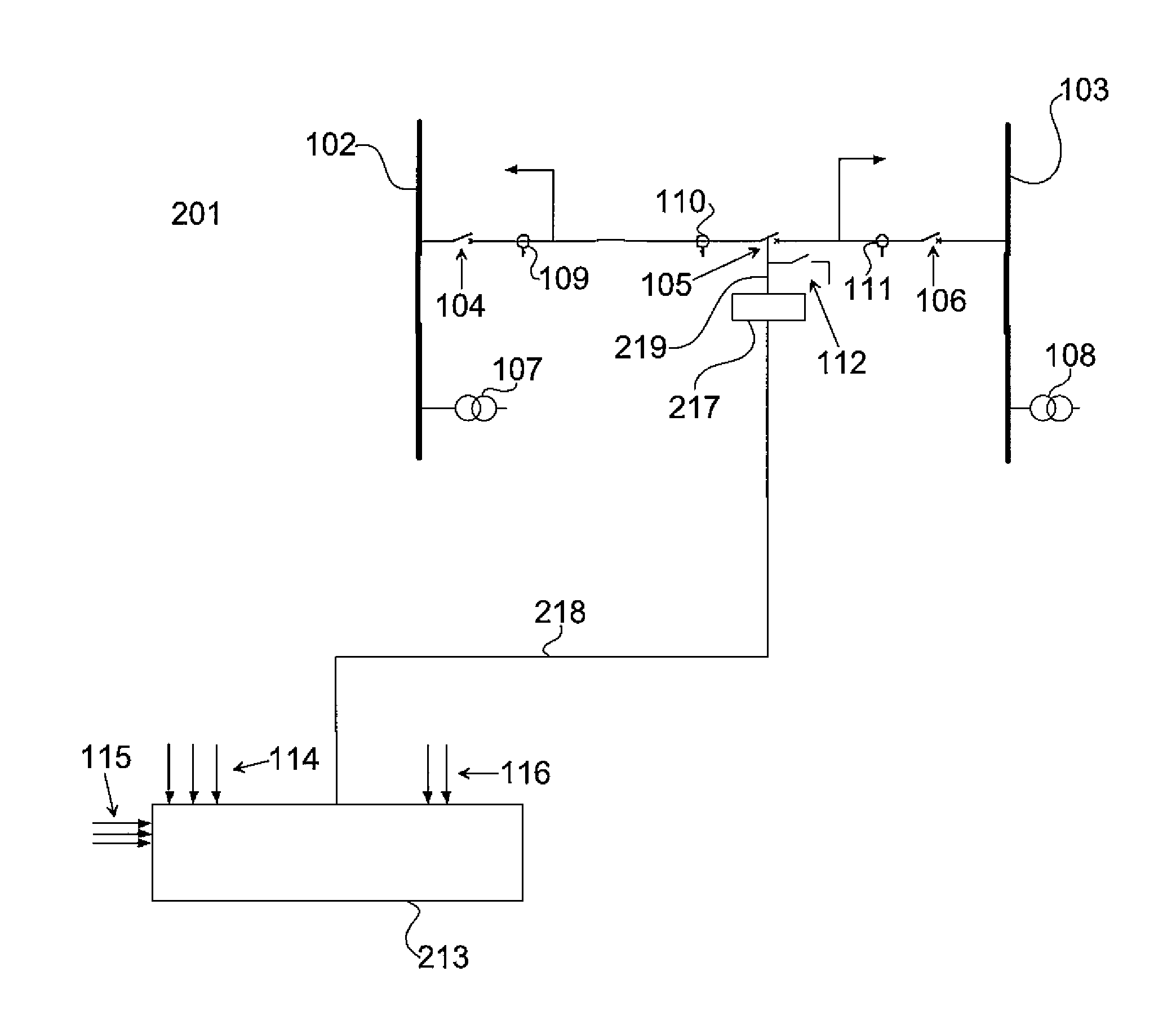
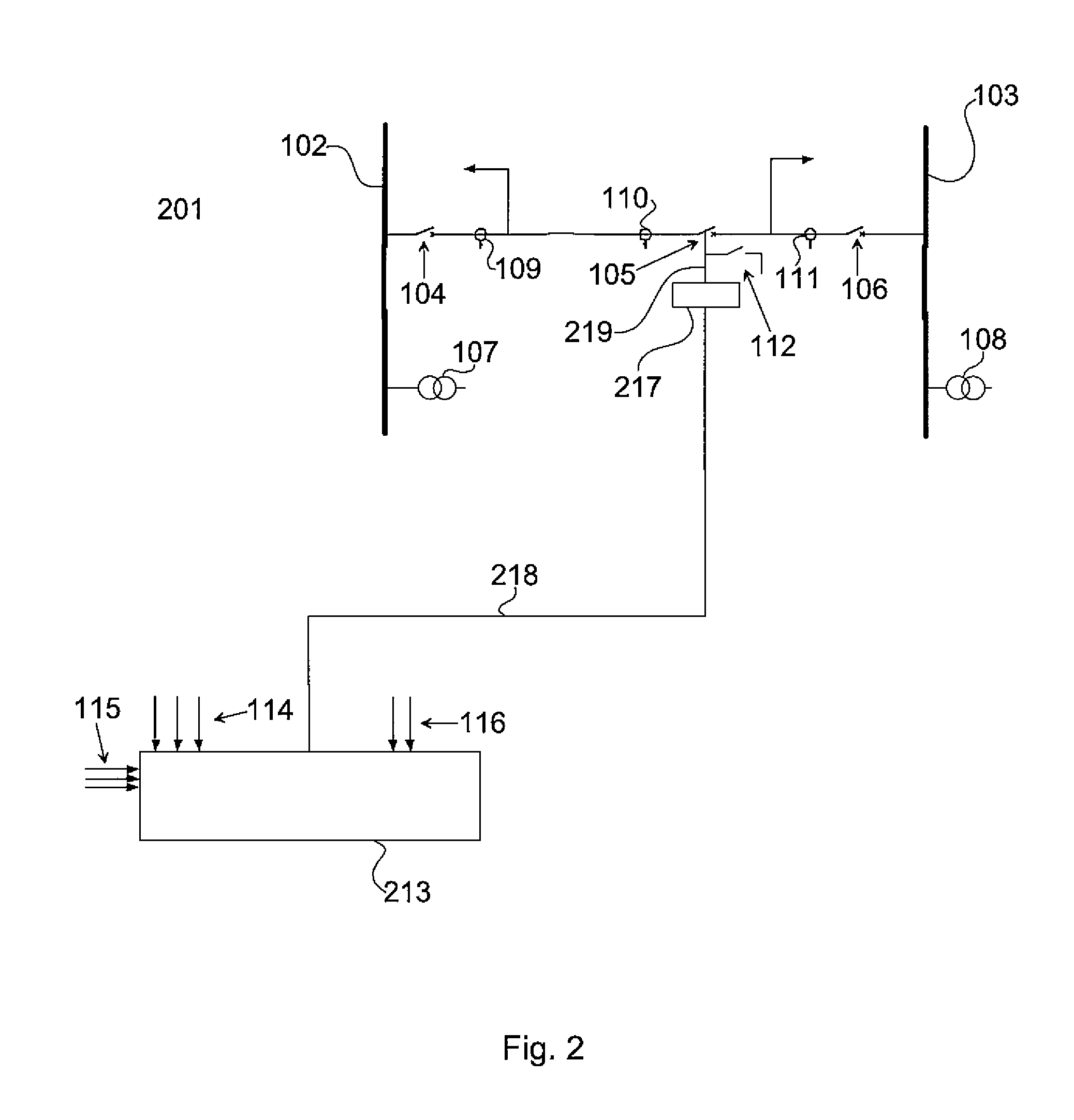
[0024]FIG. 2 illustrates schematically, partly in a block diagram, partly in a circuit diagram, a portion of a circuit breaker station in which a control arrangement according to an embodiment of the present invention is implemented.

[0025]The circuit breaker station 201 comprises a plurality of circuit breakers 104, 105, 106, voltage measuring devices 107, 108 for measuring voltages of bus bars 102, 103, current measuring devices 109, 110, 111 for measuring currents through the circuit breakers 104, 105, 106, and, for each circuit breaker 104, 105, 106, a circuit breaker position indicating device 112 for indicating the position of the circuit breaker 104, 105, 106. Note that for reasons of clarity only one circuit breaker position indicating device 112 is illustrated in FIG. 2.

[0026]The control arrangement according to an embodiment of the invention comprises a central control system 213 for the overall control of the circuit breaker station 201. The central control system 213 is c...


PUM


Abstract

A control arrangement for a circuit breaker station includes a central control system and, for each of the circuit breakers, a circuit breaker operating unit connected to the central control system to obtain switching instructions and to the respective circuit breaker to control the operation thereof. The central control system and the circuit breaker operating units each have a local clock that are synchronized with one another. The central control system is, during use, arranged to calculate a point of time for switching each of the circuit breakers based on measured voltages, currents, and circuit breaker positions, and to send the point of time in a switching instruction to the circuit breaker operating unit. Each of the circuit breaker operating units is arranged to switch the circuit breaker, to which it is connected, at the point of time which is received in the switching instruction from the central control system.

Description

TECHNICAL FIELD OF THE INVENTION[0001]The present invention relates to a control arrangement for a circuit breaker station or substation.DESCRIPTION OF RELATED ART AND BACKGROUND OF THE INVENTION[0002]Voltage and current transients generated during switching of high voltage circuit breakers are of increasing concern for the electric utility industry. These concerns include both power quality issues for voltage-sensitive customer loads, and excessive stresses on power system equipment. Conventional solutions for reducing switching transients include circuit breaker pre-insertion devices such as resistors or inductors and fixed devices such as arresters and current limiting reactors. While these solutions provide some degree of mitigation, they require additional equipment, increase costs and are accompanied by reliability concerns.[0003]A superior approach to reduced switching transients is synchronous switching, sometimes referred to as point-on-wave switching. Synchronous switching...

Claims


Application Information

Patent Timeline
Patent Type & Authority Applications(United States)
IPC IPC(8): H02J11/00
CPCH01H9/56H02J11/00H01H33/596H01H33/593
Inventor BJORKLUND, HANS
Owner HITACHI ENERGY SWITZERLAND AG
Why Eureka
Try Eureka