Configurable pitch reducing optical fiber array

a technology of optical fiber array and configuration, applied in the field of couplers, can solve the problems of increasing insertion loss, reducing coupling coefficient at each interface, and significant challenges in interfacing optical high na waveguide devices

Inactive Publication Date: 2013-08-22
KOPP VICTOR ILICH +4
View PDF0 Cites 62 Cited by
  • Summary
  • Abstract
  • Description
  • Claims
  • Application Information

AI Technical Summary

Problems solved by technology

However, there are significant challenges in interfacing optical high NA waveguide devices, including chiral optical fiber devices, with conventional low index contrast optical fibers.
Failure to properly address these obstacles results in increased insertion losses and a decreased coupling coefficient at each interface.
There are a number of significant disadvantages to this approach.
For example, a fiber cladding-capillary tube interface becomes a light guiding interface of a lower quality than interfaces inside standard optical fibers and, therefore, can be expected to introduce optical loss.
Furthermore, the capillary tube must be fabricated using a costly fluorine-doped material, greatly increasing the expense of the coupler.
Nevertheless, a number of challenges still remained.
With the proliferation of optical devices with multiple waveguide interfaces (g., waveguide arrays), establishing low-loss high-accuracy connections to arrays of low or high NA waveguides often provide problematic, especially because the spacing between the waveguides is very small making coupling thereto all the more difficult.
While the '099 Patent already teaches the coupler, which is capable to independently control waveguide NAs and channel-to-channel spacing, it did not specifically address the full extent of configurability with respect to interfacing with plurality of optical fibers, possible use of its disclosed novel structures and inventive methodologies for fabrication thereof.

Method used


Image

  • Configurable pitch reducing optical fiber array
  • Configurable pitch reducing optical fiber array
  • Configurable pitch reducing optical fiber array

Examples


Embodiment Construction

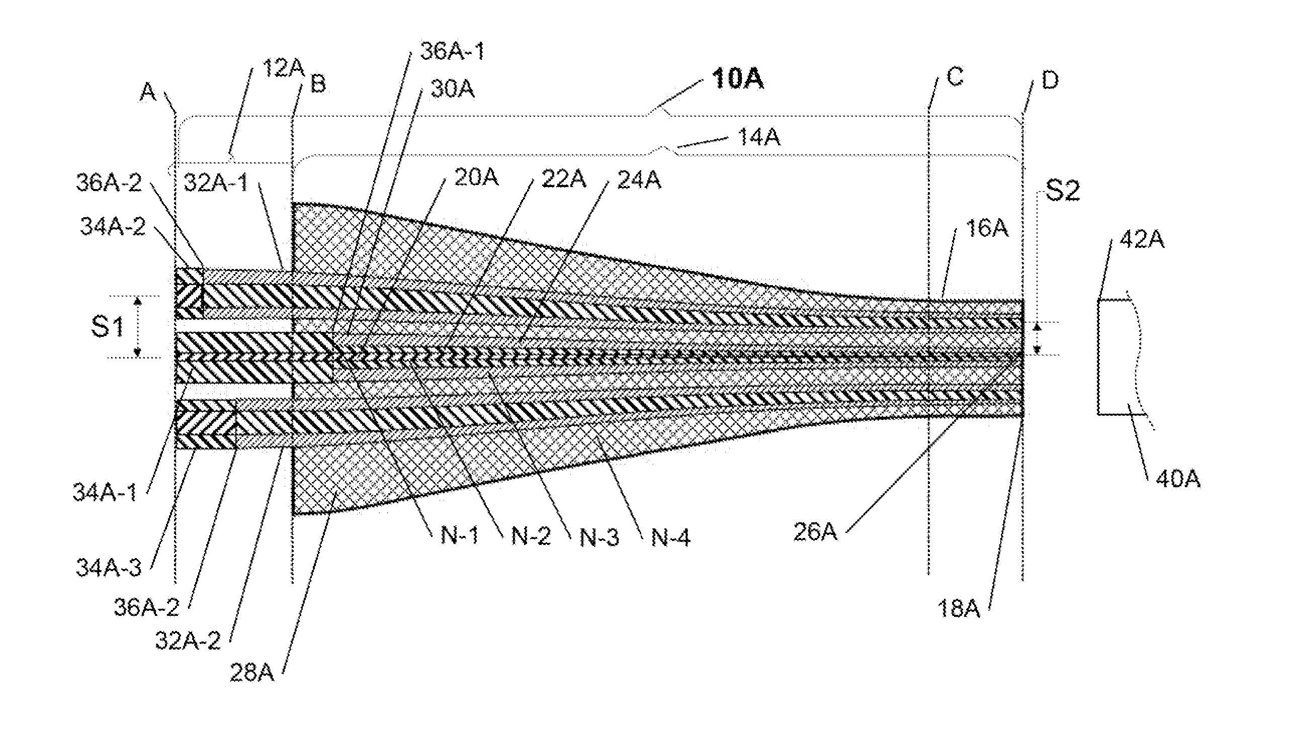
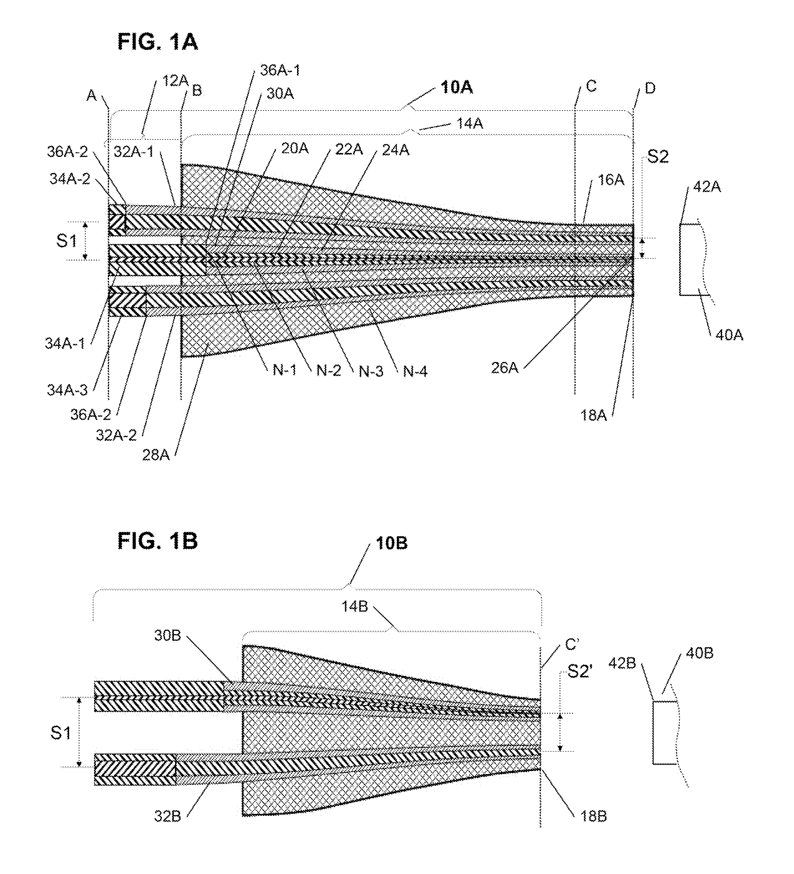
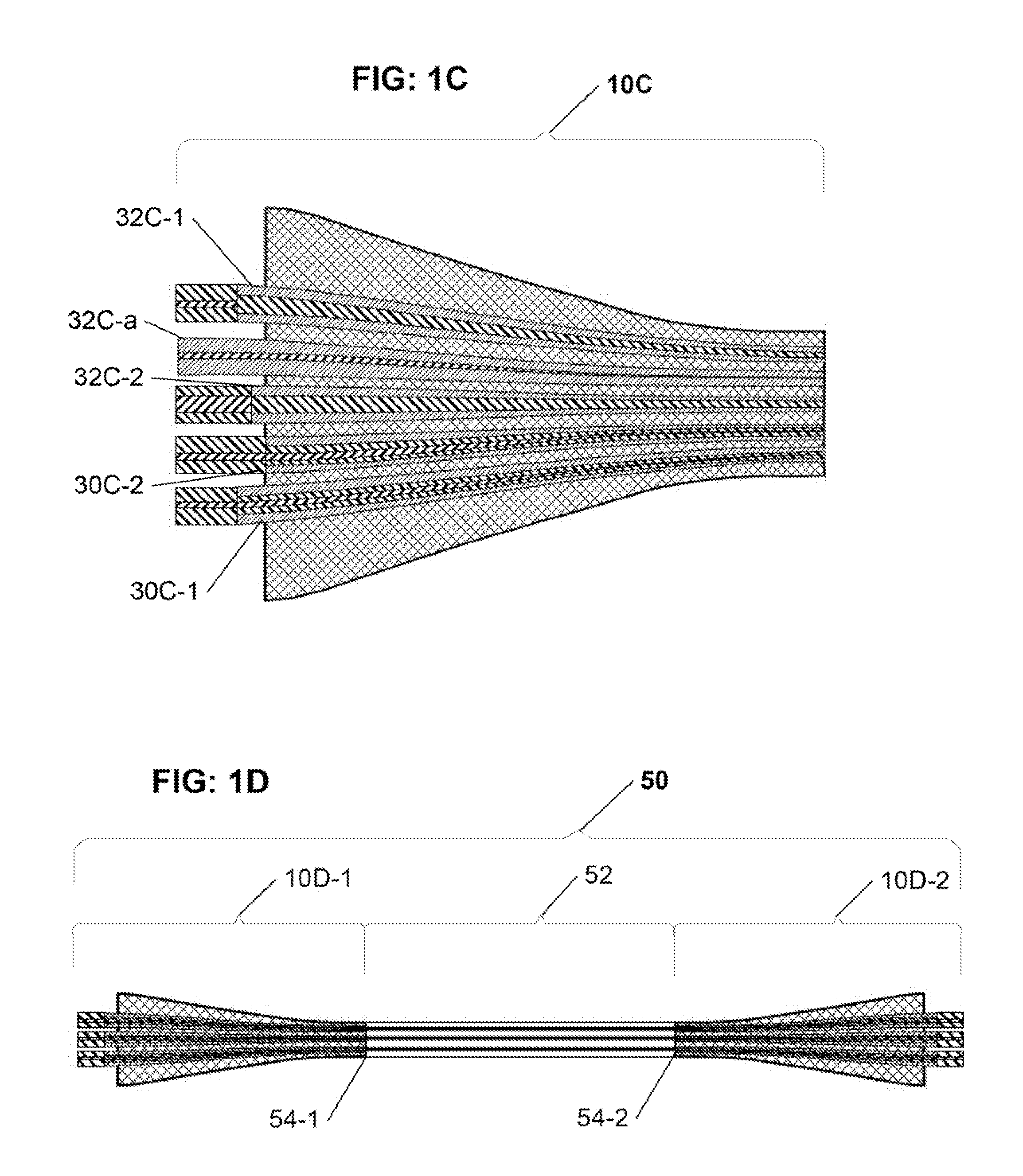
[0032]The present invention is directed to an optical fiber coupler array capable of providing a low-loss, high-coupling coefficient interface with high accuracy and easy alignment between a plurality of optical fibers (or other optical devices) with a first channel-to-channel spacing, and an optical device having a plurality of waveguide interfaces with a second, smaller channel-to-channel spacing. Advantageously, in various embodiments of the present invention, each of a larger size end and a smaller size end of the optical fiber coupler array is configurable to have a correspondingly different (i.e., larger vs. smaller) channel-to-channel spacing, where the respective channel-to-channel spacing at each of the novel optical coupler arrays larger and smaller ends may be readily matched to a corresponding respective first channel-to-channel spacing of the plural optical fibers at the larger optical coupler array end, and to a second channel-to-channel spacing of the optical device p...


PUM


Abstract

The inventive optical fiber coupler array is capable of providing a low loss, high-coupling coefficient interface with high accuracy and easy alignment between a plurality of optical fibers (or other optical devices) with a first channel-to-channel spacing, and an optical device having a plurality of closely-spaced waveguide interfaces with a second channel-to-channel spacing, where each end of the optical fiber coupler array is configurable to have different channel-to-channel spacing, each matched to a corresponding one of the first and second channel-to-channel spacing. The novel optical coupler array includes a plurality of waveguides (at least one of which may optionally be polarization maintaining), that comprises at least one gradually reduced vanishing core fiber, at least in part embedded within a common housing structure. Alternatively, the novel coupler array may be configured for utilization with at least one of an optical fiber amplifier and an optical fiber laser.

Description

CROSS REFERENCE TO RELATED APPLICATIONS[0001]The present application is a continuation-in-part of, and claims priority form, the commonly assigned co-pending U.S. patent application Ser. No. 13 / 692,989 (Atty Docket No. 1014-39-CLINK), which in turn is a continuation of, and claims priority from, the commonly assigned U.S. patent application Ser. No. 12 / 502,613—now U.S. Pat. No. 8,326,099 (Atty Docket No. 1014-39), which in turn claims priority from commonly assigned U.S. Provisional Patent Application Seer. No. 61 / 080,684 (Atty Docket No. 1014-39PROV), all of which are incorporated herein by reference in their entirety; and which further variously claims priority at least from the following commonly assigned patent applications: Application Ser. No. 61 / 606,681 (Atty Docket No. 1014-39CIP-PROV), Application Ser. No. 61 / 609,180 (Atty Docket No. 1014-39CIP-PROV2), and Application 61 / 752,311 (Atty Docket No. 1014-3CIP-S-1), all of which are also incorporated herein by reference in their...

Claims


Application Information

Patent Timeline
Patent Type & Authority Applications(United States)
IPC IPC(8): G02B6/26
CPCG02B6/26G02B6/04G02B6/02042G02B6/30G02B6/262G02B6/2804G02B6/305
Inventor KOPP, VICTOR IL'ICHSINGER, JONATHANNEUGROSCHL, DANIELPARK, JONGCHULWLODAWSKI, MITCHELL S.
Owner KOPP VICTOR ILICH
Why Eureka
Try Eureka